Spine Fixation Device and Method

a fixation device and spine technology, applied in the field of minimally invasive surgical techniques, can solve the problems of pain localized or radiating, pain necessitating treatment, chronic pain,

Inactive Publication Date: 2014-09-18
LOVELL LAVERNE
View PDF0 Cites 4 Cited by
  • Summary
  • Abstract
  • Description
  • Claims
  • Application Information

AI Technical Summary

Benefits of technology

[0005]An embodiment of the invention disclosed herein comprises of an electrocautery sliding knife, referred herein to as “ESK,” and a minimally invasive portal access device, referred herein to as “MIPAD,” enabling precise placement and purchase of a plurality of bone screws into a plurality of cervical vertebrae enabling additional hardware, such as one or more posterior cervical plates, to immobilize the vertebral bodies relative to one another.
[0006]The Electrocautery Sliding Knife is a new device enabling a novel technique whereby sliding a combined cauterizing and cutting edge down a previously placed guide rod. The guide rod, also referred to herein also as a “Docking Rod”, described in further detail below, is purchased in the cervical facet joint. The Electrocautery Sliding Knife creates a minimally invasive portal for access to the posterior lateral mass of the cervical spine. This portal receives the MIPAD, also described in further detail below, facilitating the stabilization and fusion. These devices help to eliminate the long skin incision and painful muscle dissection otherwise needed in current posterior cervical approaches.

Problems solved by technology

When the motion segment unit becomes diseased, a patient may experience localized or radiating pain or even paralysis necessitating treatment.
Failure to fuse after anterior approach results in chronic pain and necessitates repeat surgery to secure fusion and relieve this pain.

Method used


Image

  • Spine Fixation Device and Method
  • Spine Fixation Device and Method
  • Spine Fixation Device and Method

Examples


Embodiment Construction

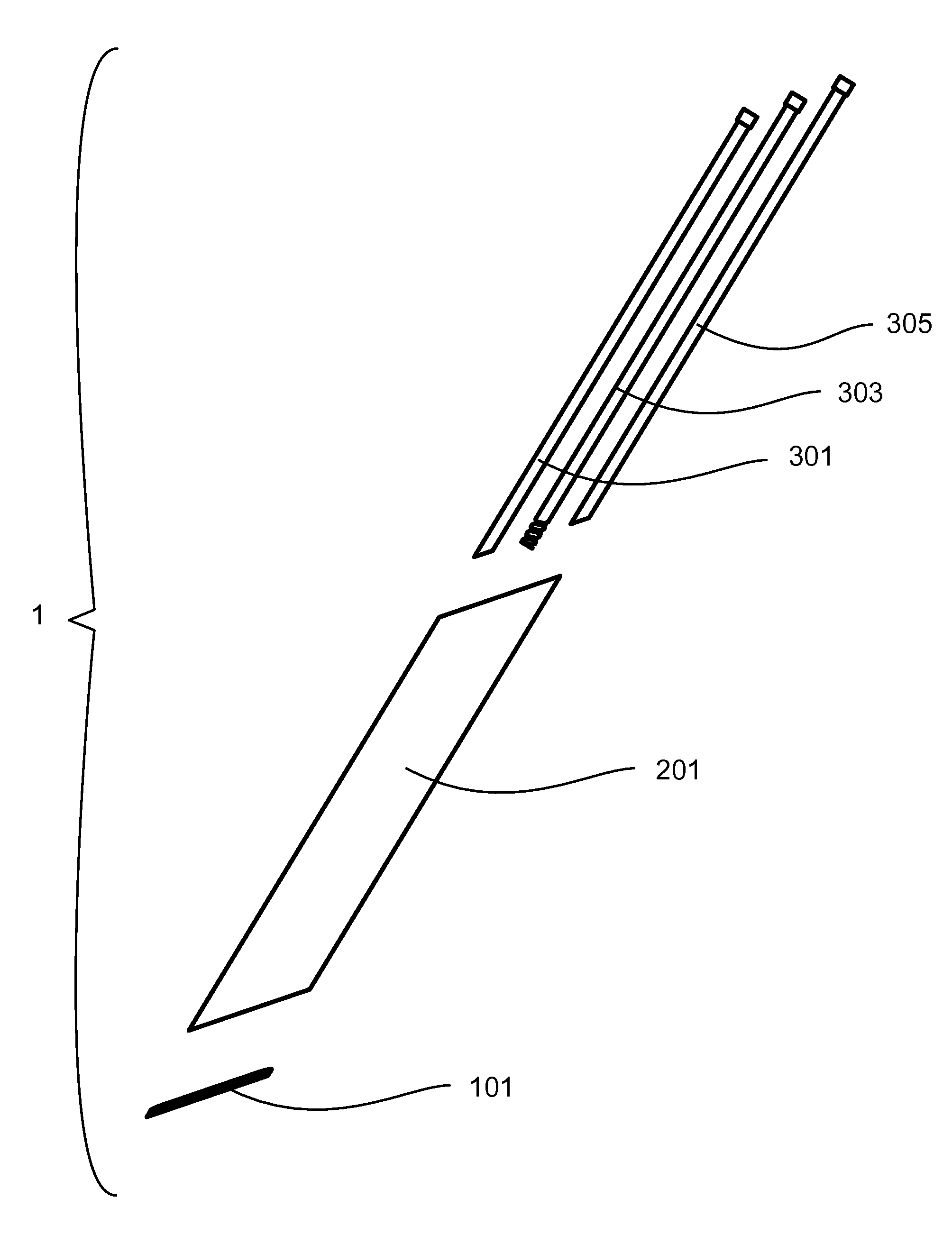
[0057]The drawings illustrate a novel device and method for surgical inducement of cervical vertebra fusion as a treatment for cervical spinal disease.

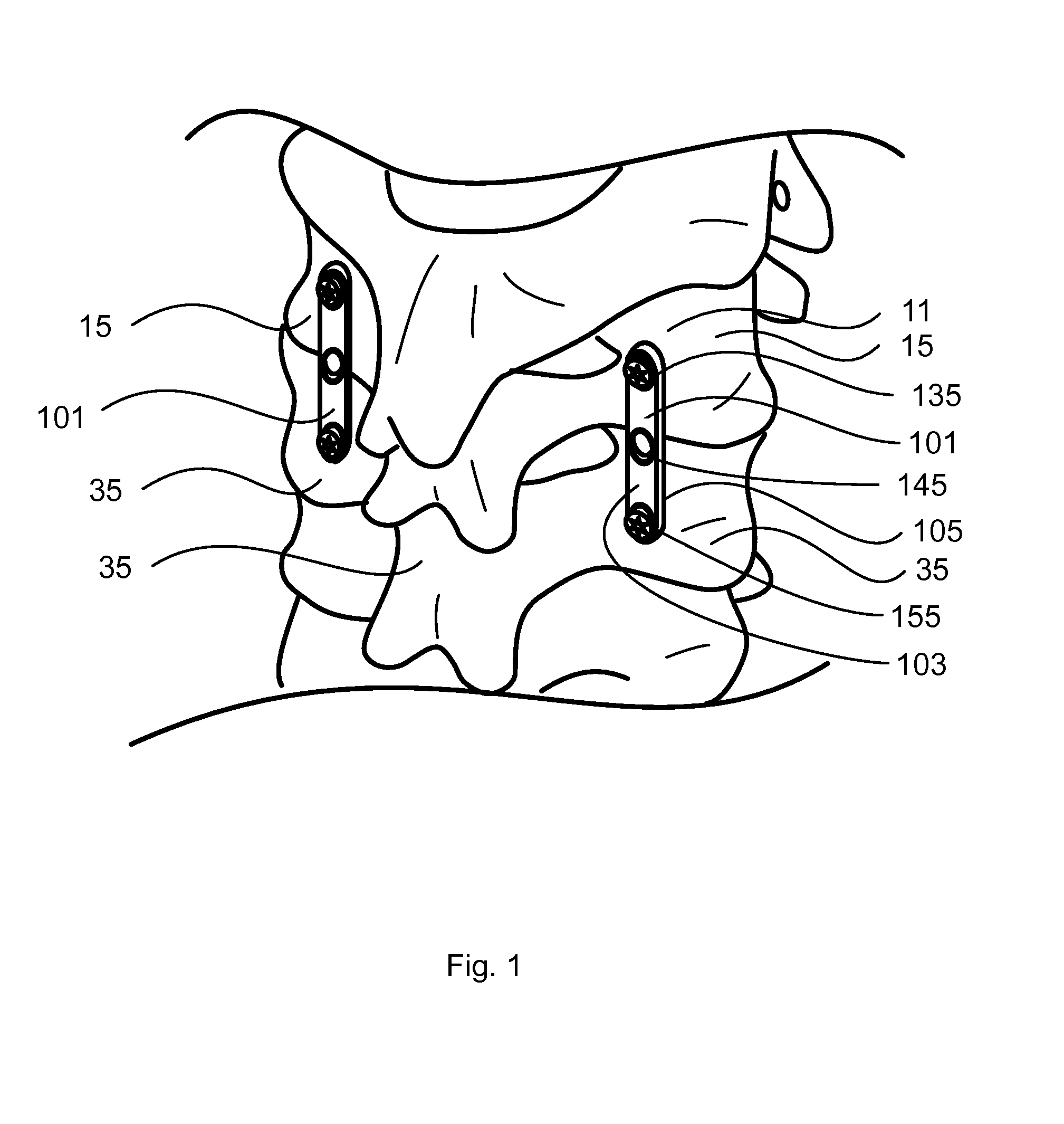
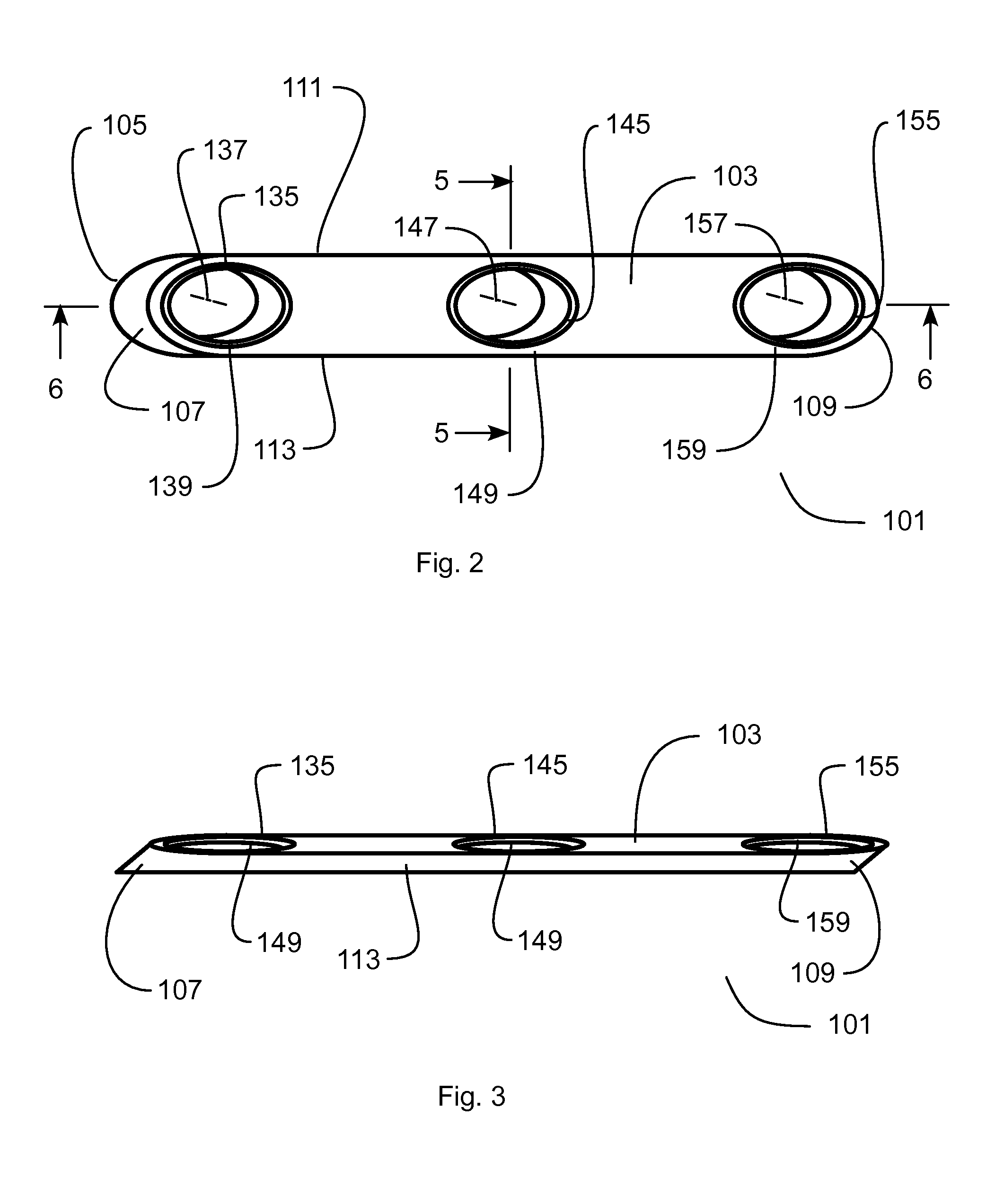
[0058]FIG. 1 shows a perspective view of the first embodiment of the present invention 1 positioned upon a cervical column of a typical patient. Skin, muscles, ligaments and blood are not illustrated in this figure for clarity and ease of understanding. The lateral mass cervical plate 101 positioned on the left is positioned upon the left posterior portion lateral masses 15, 35 of the upper and lower cervical vertebrae 11, 31 of the motion segment unit which is targeted for fusion. The plate 101, acts as an inter-vertebra linking member, rigidly connecting upper vertebra to the lower vertebra. One plate 101 may be used on either the left or right side of the vertebras, or as shown in FIG. 1, two plates 101 may be used. In the embodiment, the plate is 25 mm long by 5 mm wide. Each plate 101 possesses three apertures 135, 145, 155 exten...


PUM


Abstract

A novel device and method for surgical inducement of cervical vertebra fusion as a treatment for cervical spinal disease using a guide wire, slide knife, and a minimally invasive portal access device and an inter-vertebra linking member.

Description

BACKGROUND OF THE INVENTION[0001]This invention relates generally to devices and method for surgically immobilizing or fusing two or more human vertebral bodies. More particularly, it relates to a minimally invasive surgical technique allowing for a linear posterior approach to purchasing one or more within a vertebrae and placement of plates, rods or other such hardware to enable proper bone fusion between a plurality of vertebrae.[0002]Normally, two adjacent vertebra would usually move relative to one another creating a motion segment unit. While each motion segment unit may only move a few degrees, the collective movement of all the vertebral motion segment units allows for great flexibility of the spine. When the motion segment unit becomes diseased, a patient may experience localized or radiating pain or even paralysis necessitating treatment. Treatment of cervical spinal disease, such as disc degeneration, disc herniation, instability, spinal stenosis, spondylosis, and facet j...

Claims


Application Information

Patent Timeline
Patent Type & Authority Applications(United States)
IPC IPC(8): A61B17/70A61B18/08
CPCA61B18/082A61B17/7064A61B17/7059A61B17/16A61B2018/00196A61B2018/00595A61B2018/00601A61B2018/1412A61B2090/376
Inventor LOVELL, LAVERNE
Owner LOVELL LAVERNE
Why Eureka
Try Eureka