

Fluid ejection device
a technology of ejection device and fluid, which is applied in the direction of fluid jet surgical cutter, combustion type, lighting and heating apparatus, etc., can solve the problems of fluid temperature rise, fluid of suitable temperature cannot be ejected to the affected part, and fluid temperature ris
- Summary
- Abstract
- Description
- Claims
- Application Information
AI Technical Summary
Benefits of technology
Problems solved by technology
Method used
Image

Examples
first embodiment
A. First Embodiment
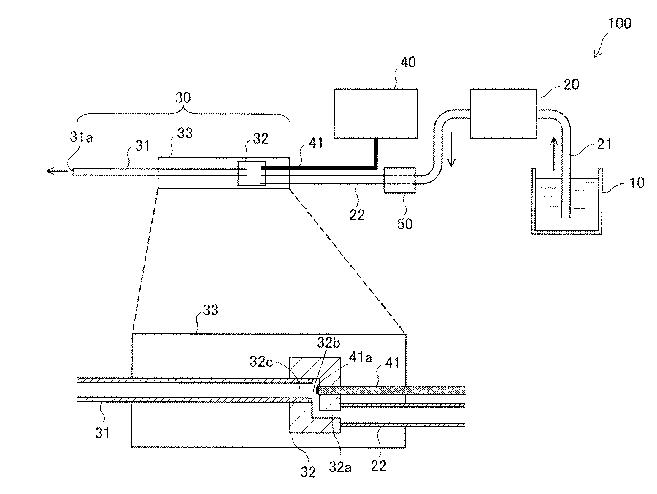
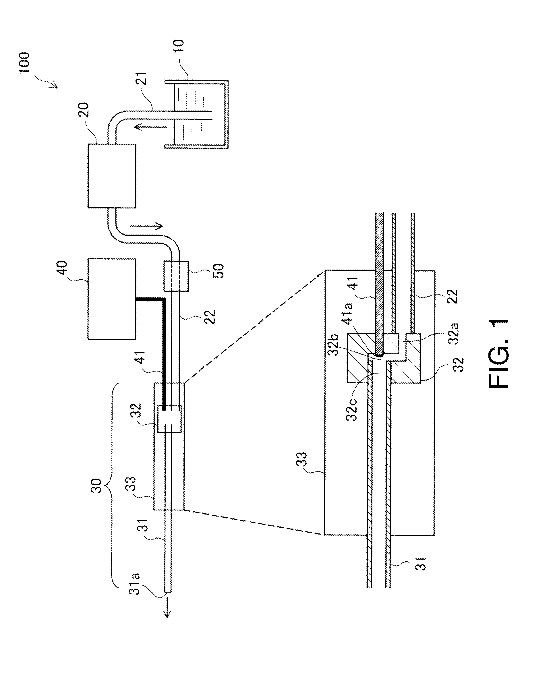
[0028]FIG. 1 is an explanation view showing a structure of a fluid ejection device 100 of an embodiment of the invention.
[0029]The fluid ejection device 100 of this embodiment is a medical apparatus used in a medical institution, and has a function as a scalpel to incise or excise an affected part by ejecting a fluid to the affected part.
[0030]The fluid ejection device 100 includes a fluid container 10, a fluid supply mechanism 20, a hand piece 30, a laser oscillation part 40 and a cooling circuit 50. Incidentally, in FIG. 1, the inner structure of a part of the hand piece 30 is enlarged and shown.
[0031]The fluid container 10 and the fluid supply mechanism 20 are connected by a connection tube 21, and the fluid supply mechanism 20 and the hand piece 30 are connected by a connection tube 22. In this embodiment, the connection tubes 21 and 22 are made of resin. The hand piece 30 and the laser oscillation part 40 are connected by an optical fiber cable 41.
[0032]The f...
second embodiment
B. Second Embodiment
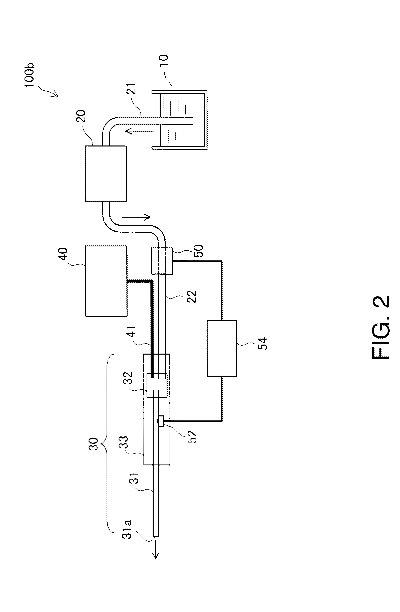
[0046]FIG. 2 is an explanatory view showing a structure of a fluid ejection device 100b of a second embodiment. A main difference from the first embodiment shown in FIG. 1 is that a temperature sensor 52 is provided in a fluid ejection tube 31, and a control part 54 is provided. The other structure is the same as that of the first embodiment.
[0047]The temperature sensor 52 measures the temperature of fluid in the fluid ejection tube 31. The control part 54 performs feedback control of a cooling circuit 50 so that the temperature of the fluid measured by the temperature sensor 52 falls within a previously set temperature range.
[0048]According to the second embodiment, the same effects as those of the first embodiment can be obtained, and the temperature of the fluid ejected from the fluid ejection tube 31 can be made to fall within the suitable range.
[0049]Incidentally, the temperature sensor 52 may be provided at a place where the temperature of the fluid can be ...
modified example 1
[0051]In the above embodiment, the irradiation part 41a of the tip of the optical fiber cable 41 is provided inside the pulsation applying part 32. The pulsation applying part 32 maybe constructed of a fluid chamber connected to the fluid ejection tube 31 and a piezoelectric element to change the volume of the fluid chamber. When a drive voltage is applied to the piezoelectric element, the temperature of the piezoelectric element rises, and the heat of the piezoelectric element is conducted to the fluid chamber. Thus, even when the pulsation applying part 32 is constructed of the fluid chamber and the piezoelectric element, the temperature of the fluid rises. Accordingly, the invention can be applied also to the fluid ejection device 100 in which the pulsation applying part 32 is constructed of the fluid chamber and the piezoelectric element.
PUM
 Abstract
Description
Claims
Application Information