Check patentability & draft patents in minutes with Patsnap Eureka AI!

Manufacturing method of liquid ejecting head

a manufacturing method and liquid ejector technology, applied in the field of manufacturing methods of liquid ejectors, can solve the problems of not only the manufacturing method, but the piezoelectric property of the piezoelectric layer is decreased, and achieve the effect of preventing the decrease of adhesiveness, preventing the damage of the piezoelectric actuator, and efficient hydrogen adsorption

Active Publication Date: 2014-09-25
SEIKO EPSON CORP
View PDF1 Cites 0 Cited by
  • Summary
  • Abstract
  • Description
  • Claims
  • Application Information

AI Technical Summary

Benefits of technology

The invention provides a method to make a liquid ejecting head without damaging the piezoelectric element caused by hydrogen. By using a protection material containing a nitro compound, the hydrogen gas generated during the process of wet etching is adsorbed, preventing damage to the actuator. The protection material is solid when disposed, preventing adhesiveness issues, and it is liquid during the wet etching, allowing for efficient hydrogen adsorption. The nitro compound can be easily set in a solid form at room temperature and in a liquid form at the wet etching temperature. The flow path formation substrate is preferably made of silicon and wet etching is performed using potassium hydroxide, allowing for high precision in forming the pressure generation chamber.

Problems solved by technology

However, if the wet etching of the flow path formation substrate which is formed of a silicon single-crystal substrate is performed with the etching solution formed of an alkaline aqueous solution such as potassium hydroxide (KOH), hydrogen gas is generated and damages a piezoelectric layer so that a piezoelectric property of the piezoelectric layer is decreased.
Such a problem does not only occur in the manufacturing method of the ink jet type recording head, but also occurs in a manufacturing method of a liquid ejecting head which ejects liquid other than ink.

Method used


Image

  • Manufacturing method of liquid ejecting head
  • Manufacturing method of liquid ejecting head
  • Manufacturing method of liquid ejecting head

Examples


embodiment 1

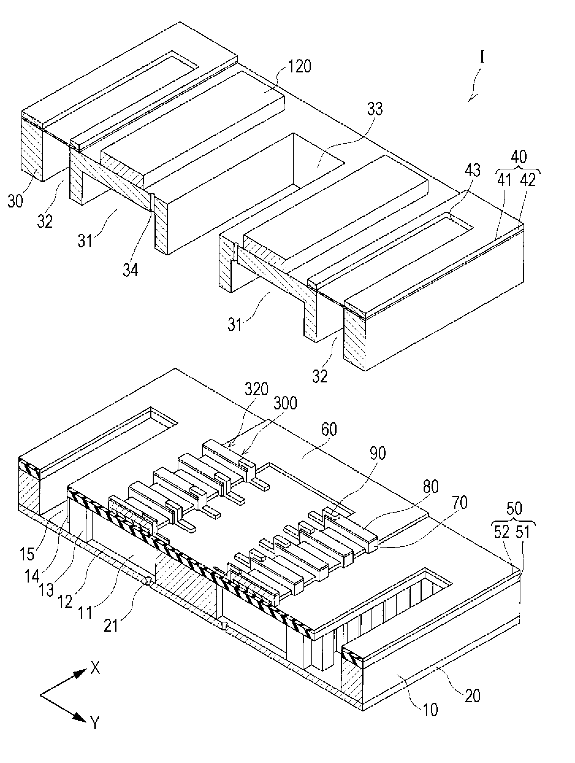
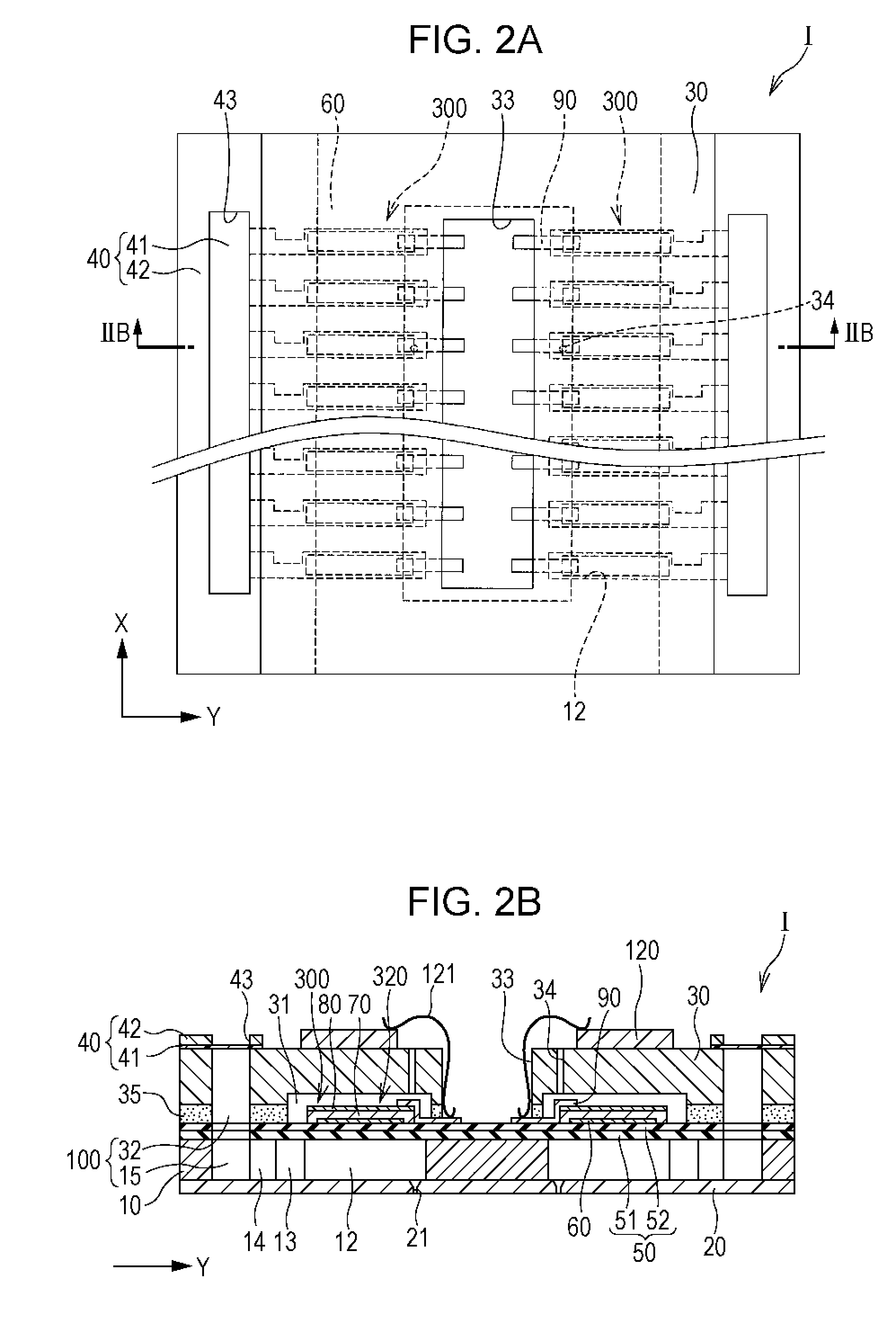
[0022]FIG. 1 is an exploded perspective view showing a schematic configuration of an ink jet type recording head which is an example of the liquid ejecting head according to Embodiment 1 of the invention and FIGS. 2A and 2B are a plan view of FIG. 1 and a cross-sectional view taken along line IIB-IIB, respectively.

[0023]As shown in the drawings, in the embodiment, a flow path formation substrate 10 included in an ink jet type recording head I which is an example of the liquid ejecting head of the embodiment is, for example, formed of a substrate including a silicon material, for example, a single-crystal silicon substrate or a polycrystal silicon substrate. In the flow path formation substrate 10, pressure generation chambers 12 which are partitioned by a plurality of partition walls 11 are provided in a line along a direction in which a plurality of nozzle openings 21 ejecting ink are provided in a line. Hereinafter, this direction is referred to as a direction in which the pressur...


PUM


Abstract

A piezoelectric actuator which is provided on the flow path formation substrate, and a protection substrate which is bonded to the flow path formation substrate on the piezoelectric actuator side, the method including: bonding the flow path formation substrate on which the piezoelectric actuator is formed, and the protection substrate to form a bonded body; bonding a sealing member to the protection substrate of the bonded body on the surface side opposite the flow path formation substrate, and disposing a protection material containing a nitro compound in a space between the sealing member and the protection substrate.

Description

BACKGROUND[0001]1. Technical Field[0002]The present invention relates to a manufacturing method of a liquid ejecting head which ejects liquid from nozzle openings, particularly a manufacturing method of an ink jet type recording head which discharges ink as liquid.[0003]2. Related Art[0004]There is a known ink jet type recording head which is the liquid ejecting head including a flow path formation substrate in which a pressure generation chamber communicating with nozzle openings is formed, a piezoelectric actuator which is provided on one surface side of the flow path formation substrate, and a protection substrate which is bonded to the flow path formation substrate on the piezoelectric actuator side.[0005]In addition, such an ink jet type recording head is manufactured by forming the piezoelectric actuator on the flow path formation substrate which is formed of a silicon single-crystal substrate, then bonding the protection substrate to the upper portion thereof, and then, in a ...

Claims


Application Information

Patent Timeline
Patent Type & Authority Applications(United States)
IPC IPC(8): B41J2/16
CPCB41J2/1607B41J2/161B41J2/1623B41J2/1629B41J2/1645B41J2/1646B41J2002/14241B41J2002/14419
Inventor ASADA, KOJI
Owner SEIKO EPSON CORP
Features
  • R&D
  • Intellectual Property
  • Life Sciences
  • Materials
  • Tech Scout
  • Unparalleled Data Quality
  • Higher Quality Content
  • 60% Fewer Hallucinations
Learn More