Unit for rotating cable spacing plates in a wind turbine tower

a technology for wind turbines and towers, applied in the direction of propellers, water-acting propulsive elements, propellers, etc., can solve the problems of increasing the temperature of cables, increasing the wear on cables, and reducing the lifetime of cables, so as to reduce the stress on cables. , the effect of reducing the stress

Inactive Publication Date: 2014-09-25
ENVISION ENERGY DENMARK
View PDF10 Cites 15 Cited by
  • Summary
  • Abstract
  • Description
  • Claims
  • Application Information

AI Technical Summary

Benefits of technology

[0051]The guiding means may be a number of fingers or protrusions arranged along the periphery of the cable spacing plate. The fingers extend in a radial direction outwards from the cable spacing plate and may form a number of open ended areas between the fingers which are configured to receive at least one of the cables. The open area may have a depth and / or width which more or less correspond to the thickness of the cable or group of cables located in that area. This allows the cables to hang loosely or uncoupled in the open area which minimizes the stresses in the cables normally occurring when the cables are twisted. The open area may be closed off by a clamping band, ring, or wire arranged along the free ends of the fingers. The stresses may be reduced even further by providing the fingers with one or more curved side surfaces, e.g.,forming a plano-convex or biconvex shape where the thickness of the finger increases from the ends and towards the middle.
[0052]The guiding means may instead be a number of through holes arranged in the cable spacing plate which define a closed off area in which the cables may be located. The through holes may have a diameter which more or less corresponds to the thickness of the cable or group of cables located in that hole. The cables may be arranged in small bundles where at least one bundle may be placed in each of the holes. The holes may either be arranged with a certain distance between each hole or arranged in groups of at least two with a certain distance between each group. The cables may hang freely or loosely in the holes or may be held in place relative to the cable spacing plate, e.g.,by clamping means or a bushing / sleeve located on one or both side surfaces of that plate or by simply friction between the cables and the side surface of the hole. The holes may be arranged near the periphery and / or the middle of the cable spacing plate. This keeps the cables at an acceptable temperature even when the wind turbine is producing energy at its maximum at high ambient temperatures.

Problems solved by technology

This means that the cable spacing plates in the bottom of the tower will have a tendency to be the only ones that turn when the nacelle is yawing because of the gravity acting on the cables and the spacing plates.
A high rate or portion of twist over a short length may lead to rubbing between the cables and the guided structure which increases the wear on the cables and decreases the lifetime of cables extensively.
This may also lead to clogging the cables resulting in a change of the thermal cooling conditions, thereby increasing the cable temperature to an unacceptable level which also decreases the lifetime of cables.
As the cables are held in place by the holes in the plates, there will be a bend in the cables below and above the plate when the cables are twisted which over time will destroy the cable and the cable has to be replaced, with down time and high costs as a consequence.
This problem is to some extend addressed by preparing the plates with holes having edges which are rounded off, but as the individual cables are twisted they will be forced towards these edges and they will wear and fail such that a short circuit might appear.
A further disadvantage is that the cables have to be installed from the bottom up or from the top down by guiding each and every cable through a number of holes in the plates.
This is a troublesome and time-consuming process and thus also expensive.
Another problem with the solution disclosed in U.S. Patent Application Publication 2010 / 0247326 A1 is to get rid of heat emitted from the cables because they are arranged in small bundles relatively close to each other on a relative small plate.
A small diameter demands less travel of the cables and vice versa, but it will increase the deformation of the cables and also stresses the cables.
This configuration has the drawback that the contacting surfaces form a number of sharp edges which will damage the insulation of the cables and eventually causing the cables to fail.
Furthermore, since the cables are held in place by the clamping band, there will be a bending of the cables at both sides of the cables spacer.
This will also damage the cable over time.
This solution also suffers from the drawbacks of wear and bending as discussed above.
Thus, there is a high risk that one of the cables will glide out of its position between the fingers.

Method used


Image

  • Unit for rotating cable spacing plates in a wind turbine tower
  • Unit for rotating cable spacing plates in a wind turbine tower
  • Unit for rotating cable spacing plates in a wind turbine tower

Examples


Embodiment Construction

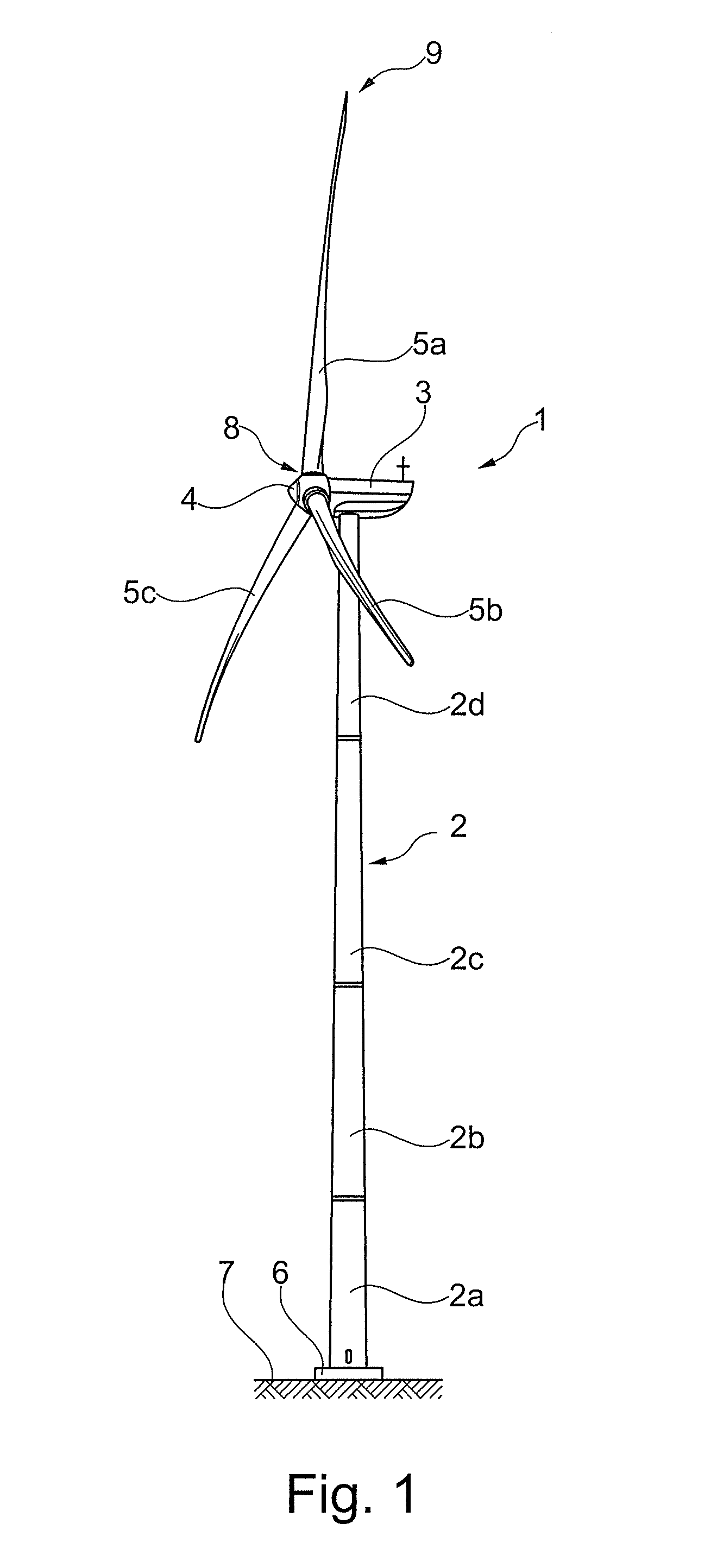
[0063]In the following text, the figures will be described one by one and the different parts and positions seen in the figures will be numbered with the same numbers in the different figures. Not all parts and positions indicated in a specific figure will necessarily be discussed together with that figure.

[0064]FIG. 1 shows an exemplary embodiment of a wind turbine 1 comprising a wind turbine tower 2 and a nacelle 3 arranged at top of the wind turbine tower 2. The nacelle 3 may be coupled to one or more yaw bearings (not shown) located at the top of the wind turbine tower 2 so that the nacelle 3 may yaw relative to the wind turbine tower 2. A separate circuit (not shown) configured to determine the yawing or twist of the nacelle 3 relative to its initial position may be coupled to the yaw bearing. The wind turbine tower 2 may comprise one or more tower sections 2a-d mounted on top of each other. A rotor hub 4 may be rotatably mounted to the nacelle 3 via a rotor shaft (not shown). ...


PUM


Abstract

A wind turbine having a wind turbine tower with a nacelle provided on the top to which a rotor hub with one or more wind turbine blades is rotatable mounted. A cable twisting system is arranged inside the wind turbine tower and suspended from the bottom of the nacelle. The cable twisting system comprises a number of cable spacing plates having a number of guiding means for guiding the electrical cables from the nacelle to the bottom of the wind turbine tower. A first and second element having engaging fingers configured to be brought into contact with each other are coupled to two adjacent cable spacing plates. The first element rotates relative to the second element when the nacelle is yawing, bringing the fingers into contact with each other. The two elements then rotate together as the nacelle continues to yaw in the same direction.

Description

BACKGROUND OF THE INVENTION[0001]1. Field of the Invention[0002]The present invention relates to a wind turbine comprising:[0003]a wind turbine tower having an inner side, a bottom, and a top;[0004]a nacelle arranged at the top of the wind turbine tower, wherein the nacelle is coupled to at least one yawing unit configured to rotate the nacelle relative to the wind turbine tower;[0005]a rotor hub rotatably mounted to the nacelle, where at least one wind turbine blade is mounted to the rotor hub;[0006]a cable twisting system configured to be arranged inside the wind turbine tower, where the cable twisting system comprises a number of cable spacing plates coupled to at least one suspension element, wherein the cable spacing plates are distributed along a length of the cable twisting system and comprise a number of guiding means configured to guide a number of electrical cables extending out from the bottom of the nacelle and into the inside of the wind turbine tower in a direction tow...

Claims


Application Information

Patent Timeline
Patent Type & Authority Applications(United States)
IPC IPC(8): F03D1/06
CPCF03D1/06F03D80/85Y02E10/72
Inventor MOESTRUP, HENNING
Owner ENVISION ENERGY DENMARK
Why Eureka
Try Eureka