
Battery system and evaluation method for battery

a battery and battery technology, applied in secondary battery servicing/maintenance, instruments, electrochemical generators, etc., can solve the problems of complex characteristic mechanism of secondary batteries and difficulty for users to accurately learn

Inactive Publication Date: 2014-09-25
WASEDA UNIV
View PDF0 Cites 16 Cited by
  • Summary
  • Abstract
  • Description
  • Claims
  • Application Information

AI Technical Summary

Benefits of technology

This patent describes a battery system and method for evaluating its performance. The system includes a secondary battery with a positive and negative electrode and electrolyte, and a section for storing information about the battery. The battery is then charged with an alternating current signal, and its impedance is measured based on the signal. This data is used to calculate the battery's deterioration degree and charging depth. The method allows for efficient and accurate evaluation of battery performance during the manufacturing process.

Problems solved by technology

However, a characteristic mechanism of the secondary battery is complicated and there is a demand for a measuring method having higher accuracy, in particular, a measuring method supported by theory.
Therefore, it is not easy for a user to accurately learn, while using a battery, a deterioration degree or a charging depth of the battery.

Method used


Image

  • Battery system and evaluation method for battery
  • Battery system and evaluation method for battery
  • Battery system and evaluation method for battery

Examples


first embodiment

Configuration of Battery System

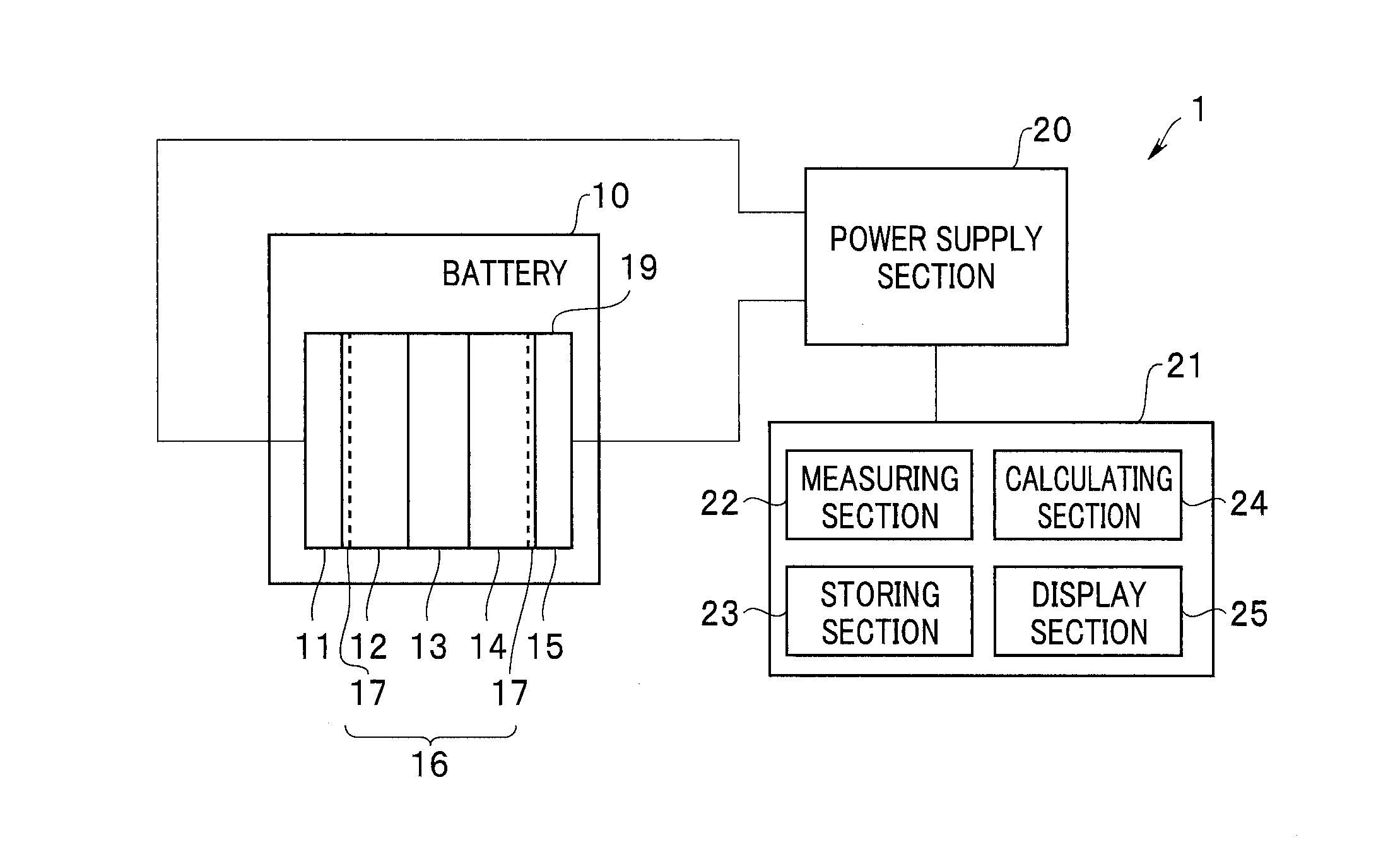
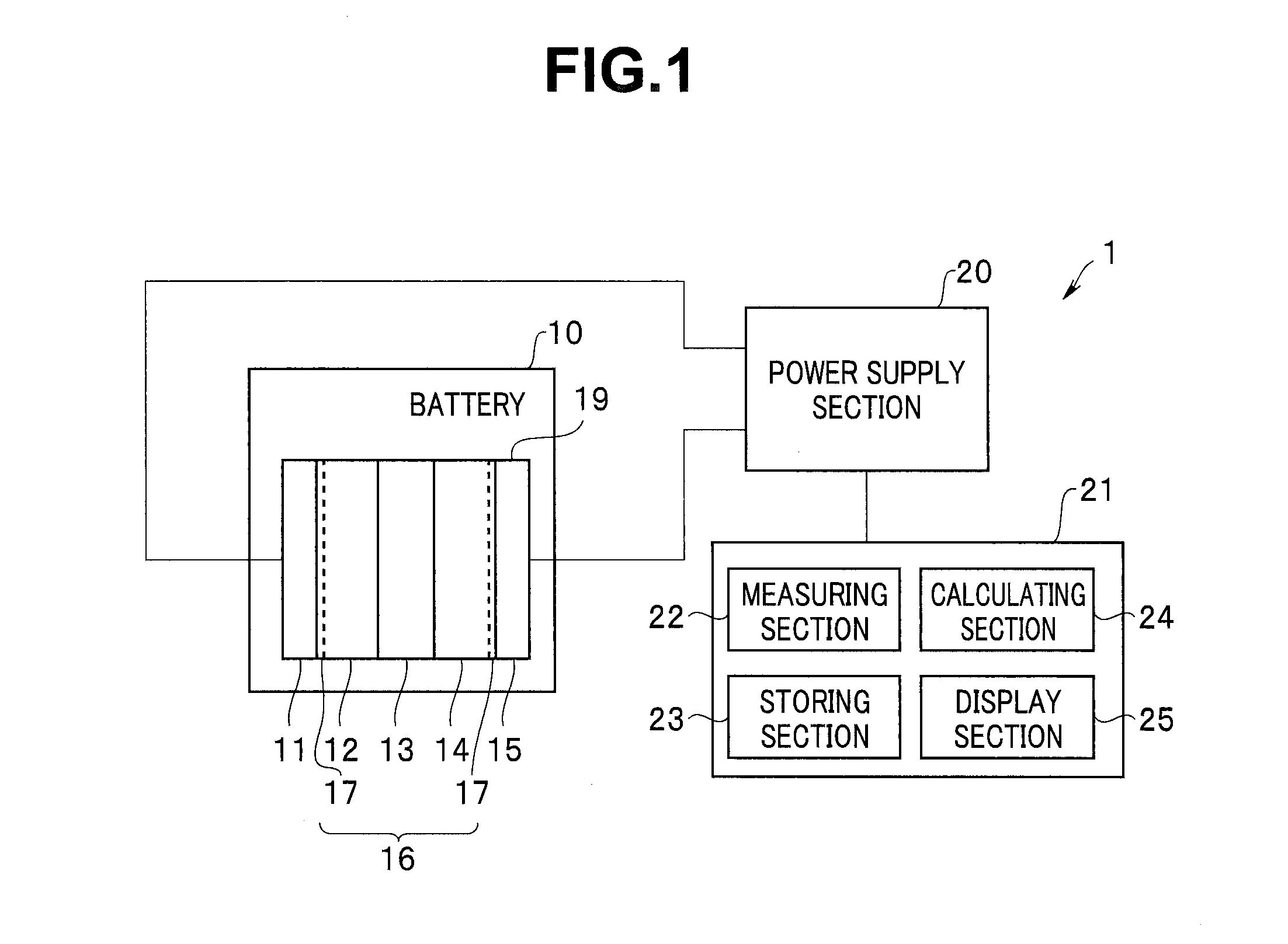
[0022]As shown in FIG. 1, a battery system 1 in a first embodiment includes a lithium ion secondary battery (hereinafter referred to as “battery”) 10, a power supply section 20, and a control section 21. The battery 10 includes a unit cell 19 including a positive electrode 11 for occluding / emitting lithium ions, electrolytes 12 and 14, a separator 13, and a negative electrode 15 for occluding / emitting lithium ions. Note that the battery 10 may include a plurality of the unit cells 19 or may include a plurality of units formed by a plurality unit cells.

[0023]The battery 10 is a lithium ion battery. The positive electrode 11 contains, for example, a lithium-cobalt oxide. The negative electrode 15 contains, for example, a carbon material. The separator 13 is formed of, for example, polyolefin. The electrolytes 12 and 14 are, for example, electrolytes obtained by dissolving LiPF6 in cyclic or chain carbonate. Note that the battery 10 may have a structure i...

second embodiment

[0073]A battery system 1A in a second embodiment is explained. Since the battery system 1A is similar to the battery system 1, the same components are denoted by the same reference numerals and signs and explanation of the components is omitted.

[0074]As shown in FIG. 11, the battery system 1A includes a cooling section 60 configured to cool a temperature of the battery 10 and a temperature measuring section 70. The battery system 1A performs impedance measurement of the battery 10 in a cooled state. A cooling temperature is preferably equal to or lower than 0° C. and particularly preferably equal to or lower than −20° C. A lower limit of the cooling temperature is not particularly specified. However, the lower limit is, for example, −30° C., which is a lower limit in battery specifications.

[0075]In FIG. 12, impedance measurement results (Cole-Cole plots) of the battery 10 not used yet at 25° C., 0° C., and −20° C. are shown. The battery 10 not used yet, that is, at a start of use ha...


PUM

PropertyMeasurementUnit
frequencyaaaaaaaaaa
frequencyaaaaaaaaaa
temperatureaaaaaaaaaa

Abstract

A battery system 1 includes a secondary battery 10 including a positive electrode 11, a negative electrode 15, and electrolytes 12 and 14, a storing section 23 configured to store peculiar information of the secondary battery 10 measured in advance including an initial resistance value and an evaluation frequency, a power supply section 20 configured to apply an alternating current signal having the evaluation frequency stored in the storing section 23 to the secondary battery 10, a measuring section 22 configured to measure impedance of a solid electrolyte interphase 17 of the secondary battery 10 from the alternating current signal, and a calculating section 24 configured to calculate at least one of a deterioration degree and a charging depth of the secondary battery 10 from the impedance and the peculiar information.

Description

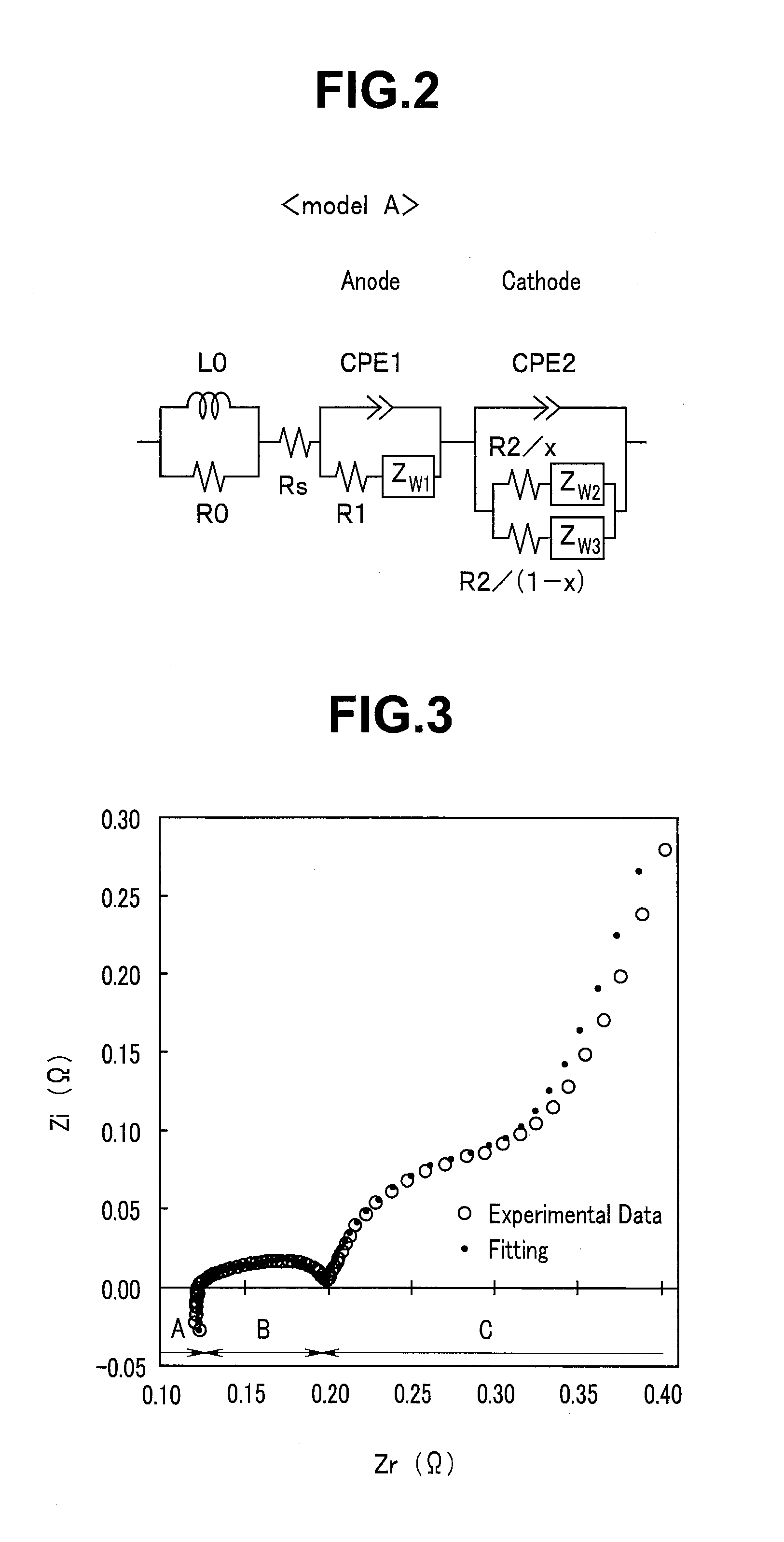
TECHNICAL FIELD[0001]Embodiments of the present invention relate to a battery system including a secondary battery and an evaluation method for a battery.BACKGROUND ART[0002]Secondary batteries are used in a portable device, an electric tool, an electric automobile, and the like. Among the secondary batteries, a lithium ion battery has a high operating voltage and can easily obtain a high output and, in addition, has a high-energy density characteristic because ionization tendency of lithium is large. Further, applications to large power supplies such as a stationary power supply and an emergency power supply are also expected.[0003]As a method of measuring characteristics of a secondary battery such as a lithium ion battery, an alternating-current impedance method is known. For example, Japanese Patent Application Laid-Open Publication No. 2009-97878 discloses a measuring method for analyzing, using an equivalent circuit model, a Cole-Cole plot of a battery acquired by an alternati...

Claims


Application Information

Patent Timeline
Patent Type & Authority Applications(United States)
IPC IPC(8): G01R31/36H01M10/42
CPCG01R31/3641H01M10/425G01R31/3627G01R31/367G01R31/385G01R31/3865G01R31/389G01R31/392H01M10/613Y02E60/10
Inventor OSAKA, TETSUYAMOMMA, TOSHIYUKIYOKOSHIMA, TOKIHIKOMUKOYAMA, DAIKICHINARA, HIROKI
Owner WASEDA UNIV
Learn More