Video transmitter, video transmission method, and program device

a video transmitter and program technology, applied in the field of video transmitters and video transmission methods, can solve the problems of radio waves, wireless system penetration through walls, interference with other wireless systems, etc., and achieve the effect of high communication rate and high transmission ra

Active Publication Date: 2014-09-25
OLYMPUS CORP
View PDF0 Cites 6 Cited by
  • Summary
  • Abstract
  • Description
  • Claims
  • Application Information

AI Technical Summary

Benefits of technology

[0014]According to a fifth aspect of the present invention, in the video transmitter related to any one of the first to fourth aspects of the present invention, the transmission output control unit may suppress the wireless transmission output during a vertical synchronization period of the wirelessly transmitted video signal.
[0015]According to a sixth aspect of the present invention, in the video transmitter related to any one of the first to fifth aspects of the present invention, the transmission output control unit may suppress the wireless transmission output at a time of wireless transmission of a control signal.
[0016]According to a seventh aspect of the present invention, in the video transmitter related to the sixth aspect of the present invention, the antenna may be an array antenna, and the transmission output control unit may suppress the wireless transmission output at a time of wireless transmission of a signal regarding control of the array antenna to the terminal.

Problems solved by technology

Depending on the material qualities of walls or the like partitioning the rooms or the frequencies of radio waves, there is a possibility of the radio waves of one wireless system penetrating through the walls and interfering with other wireless systems.
In particular, when a video signal with a high resolution such as a full HD video is wirelessly transmitted in real time, a communication rate is generally high, and thus an S / N ratio decreases and is weakened by interference.
However, when the transmission output of a video receiver is simply lowered, there is a fear of the transmission output not reaching a signal level at which the video receiver may receive a signal, thereby having a considerable influence on communication quality.
However, as described above, when the communication rate is set to be high, the communication rate is weakened by interference.
Therefore, there is a fear of the system including the video transmitter Tx3 and the video receiver Rx3 receiving the interference from the system including the video transmitter Tx1 and the video receiver Rx1.

Method used


Image

  • Video transmitter, video transmission method, and program device
  • Video transmitter, video transmission method, and program device
  • Video transmitter, video transmission method, and program device

Examples


first embodiment

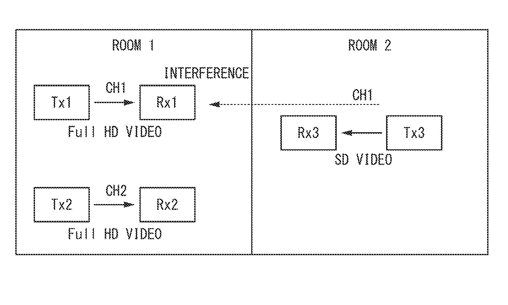
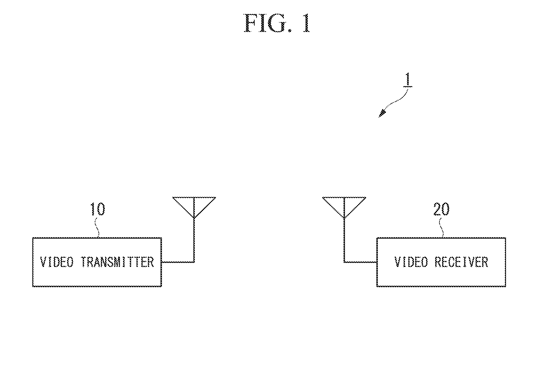
[0034]Hereinafter, a first embodiment of the present invention will be described with reference to the drawings. FIG. 1 is a schematic diagram illustrating the constitution of a video transceiver system according to the present embodiment. A video transceiver system 1 includes a video transmitter 10 and a video receiver 20. The video transmitter 10 acquires a video signal and transmits the acquired video signal to the video receiver 20 which is a connection destination. The video receiver 20 receives the video signal transmitted from the video transmitter 10 and displays a video based on the received video signal on a monitor or the like. Wireless communication is performed in a communication path between the video transmitter 10 and the video receiver 20.

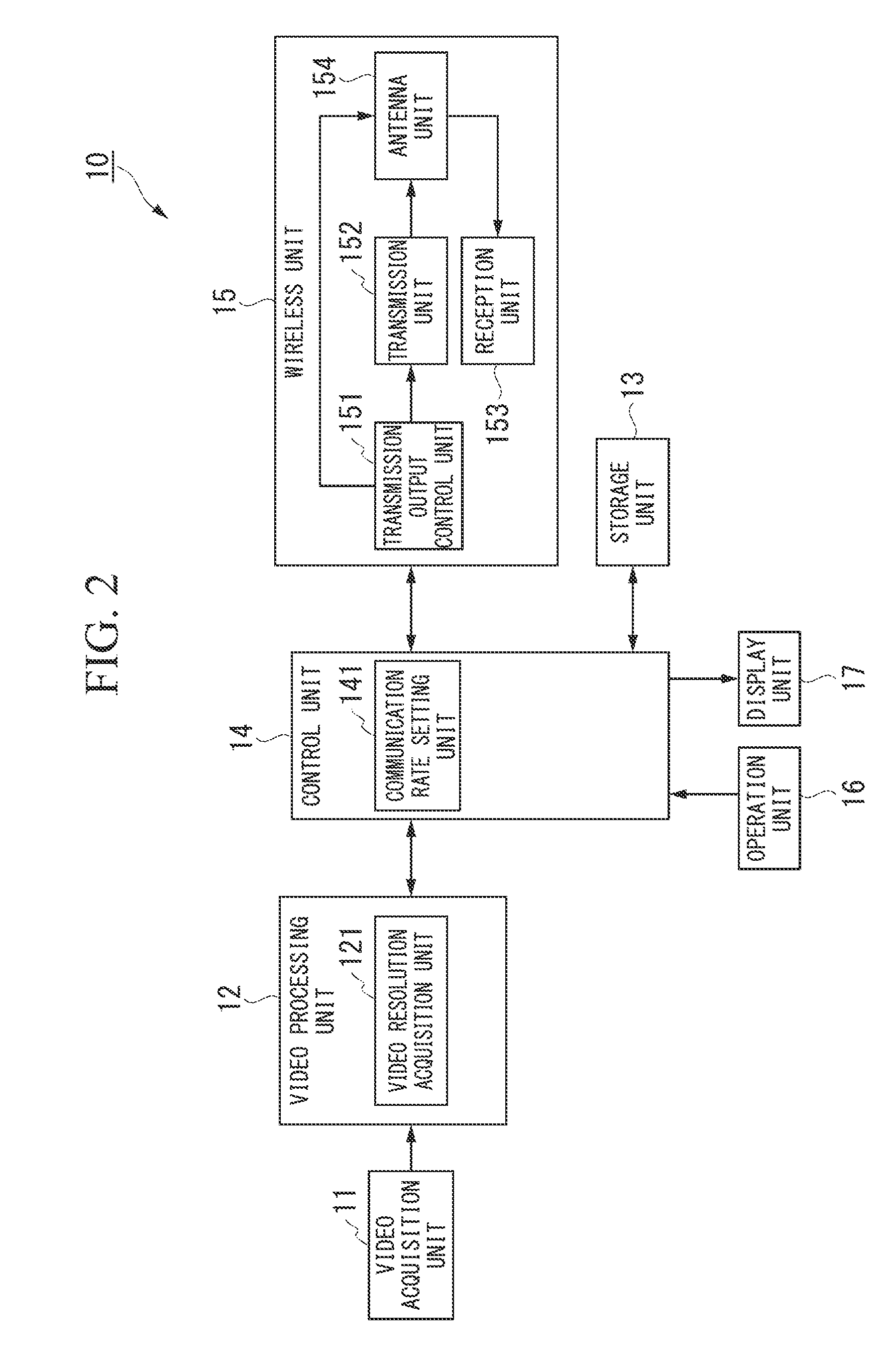
[0035]Next, the constitution of the video transmitter 10 will be described. FIG. 2 is a block diagram illustrating the constitution of the video transmitter 10 according to the present embodiment. In the illustrated example, the vi...

second embodiment

[0086]Hereinafter, a second embodiment of the present invention will be described with reference to the drawings. A difference between the present embodiment and the first embodiment is that a transmission output of a wireless signal for transmitting a control signal is also controlled in addition to the control of the transmission output of the wireless signal for transmitting the video signal in the present embodiment. In general, the control signal has less data than the video signal and a sufficiently low transmission rate. Accordingly, even when the transmission output of the wireless signal for transmitting the control signal is set to be even less compared to the transmission output of the wireless signal for transmitting the video signal, a video transmitter 10 can transmit the control signal to the video receiver 20 without receiving the influence of noise.

[0087]The constitution of a video transceiver system 1 according to the present embodiment is the same as the constitut...

third embodiment

[0093]Hereinafter, a third embodiment of the present invention will be described with reference to the drawings. A difference between the present embodiment and the first embodiment is that not only is the interference suppressed by changing the transmission output but an arrival method of an interference wave is also estimated and interference is suppressed by null steering in the present embodiment. A video transceiver system 2 according to the present embodiment includes a video transmitter 30 and a video receiver 40. As in the video transceiver system 1 according to the first embodiment, the video transmitter 30 acquires a video signal and transmits the acquired video signal to the video receiver 40 which is a connection target. The video receiver 40 displays a video based on the transmitted video signal on a monitor or the like. Wireless communication is performed in a communication path between the video transmitter 30 and the video receiver 40.

[0094]Next, the constitution of ...


PUM


Abstract

A video transmitter includes: a video resolution acquisition unit that acquires a resolution of a video signal; a wireless communication unit wirelessly transmitting the video signal and wirelessly receiving, from a terminal wirelessly receiving a video signal wirelessly transmitted, a received radio wave intensity and a minimum reception sensitivity at a time when wirelessly receiving the video signal; and a communication rate setting unit that sets a communication rate at a time when wirelessly transmitting the video signal according to the acquired resolution of the video signal. The wireless communication unit includes a transmission output control unit that controls the wireless communication unit to wirelessly transmit the video signal at the communication rate set by the communication rate setting unit and controls a wireless transmission output of the wireless communication unit to suppress a difference between the radio wave intensity and the minimum reception sensitivity.

Description

CROSS REFERENCE TO RELATED APPLICATIONS[0001]This application is a continuation application based on a PCT Patent Application No. PCT / JP2012 / 082926, filed Dec. 19, 2012, whose priority is claimed on Japanese Patent Application No. 2011-279737, filed Dec. 21, 2011, the entire content of which are hereby incorporated by reference.BACKGROUND OF THE INVENTION[0002]1. Field of the Invention[0003]The present invention relates to a video transmitter, a video transmission method, and a program.[0004]2. Description of the Related Art[0005]In video signal transmission systems between adjacent rooms, diverse wireless transmission systems have been introduced to reduce cables for transmitting video signals from the viewpoint of effective use of indoor spaces. FIG. 15 is a schematic diagram illustrating the constitutions of wireless communication systems in adjacent rooms. In the illustrated example, two rooms, Room 1 and Room 2, are adjacent to each other. In Room 1, CH1 is used to transmit dat...

Claims


Application Information

Patent Timeline
Patent Type & Authority Applications(United States)
IPC IPC(8): H04N21/436H04N21/4363H04N5/38
CPCH04N21/43615H04N21/43637H04N5/38H04B7/0617H04B7/086
Inventor KAWASAKI, SHINYA
Owner OLYMPUS CORP
Why Eureka
Try Eureka