
Repair method of repair target portion, and repair apparatus

a technology of repair target and repair target, which is applied in the direction of lamination, layered products, etc., can solve the problems of poor hardening and hinder the secure bonding of the repairing material to the repair target portion, and achieve the effect of preventing the change in the quality of the base material and sufficient heat of the repairing material

Active Publication Date: 2014-10-02
MITSUBISHI AIRCRAFT
View PDF9 Cites 7 Cited by
  • Summary
  • Abstract
  • Description
  • Claims
  • Application Information

AI Technical Summary

Benefits of technology

The present invention uses a sufficient amount of heat to harden the repairing material and minimizes thermal diffusion to the surrounding area. This ensures that the repairing material is heated properly and the base material is not compromised in quality. This allows for secure bonding of the repairing material to the repair target portion of the base material.

Problems solved by technology

If output of the external heat source is decreased in order to avoid change in quality of the base material, insufficient heating is applied to the repairing material, which results in poor hardening, and hinders secure bonding of the repairing material to the repair target portion.

Method used


Image

  • Repair method of repair target portion, and repair apparatus
  • Repair method of repair target portion, and repair apparatus
  • Repair method of repair target portion, and repair apparatus

Examples


first embodiment

[0043]Hereinafter, the present invention will be described in detail based on embodiments shown in accompanying drawings.

[0044]First, a configuration of an outer panel of an aircraft obtained by repairing will be described.

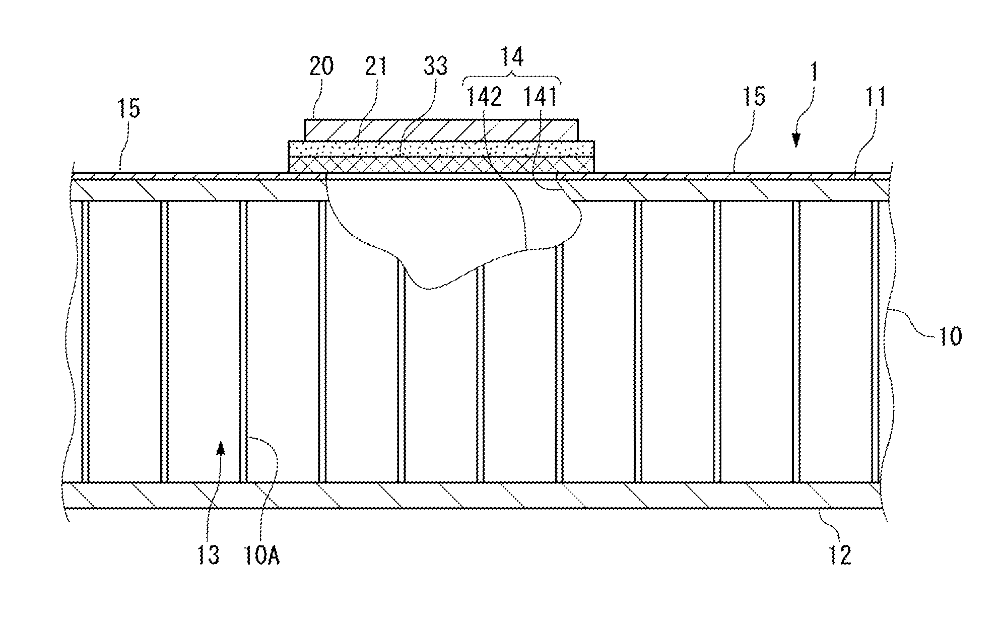
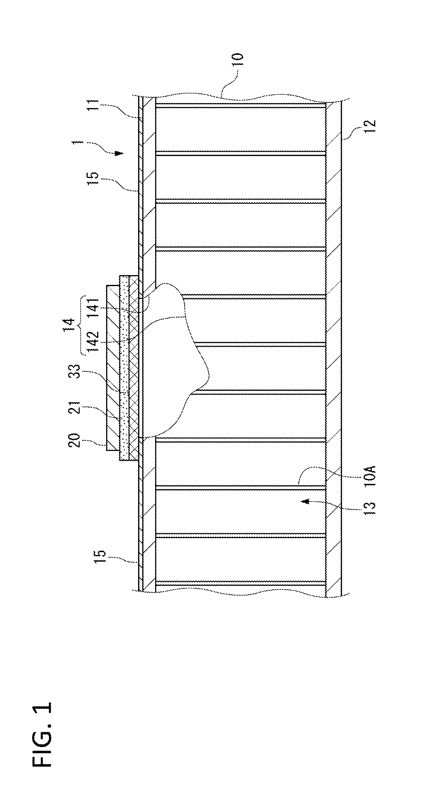
[0045]The outer panel 1 shown in FIG. 1 forms an outer surface of a wing of the aircraft. The outer panel 1 is respectively disposed on upper and lower sides of the wing with a distance therebetween, and the outer panel 1 along with spars that form a front edge and a rear edge of the wing are assembled in a box shape.

[0046]This outer panel 1 has such a structure that holds a core (core member) 10 having a honeycomb structure between two outer skins 11, 12 (honeycomb core sandwich panel). The outer panel 1 may include other layers than the core 10 and the outer skins 11, 12.

[0047]The outer panel 1 may constitute the outer surface of a fuselage of the aircraft.

[0048]The core 10 includes bulkheads 10A that form a number of cells 13 each having a hexagon cross section...

second embodiment

[0111]Hereinafter, the repair method of repairing a honeycomb core sandwich panel as the repair target will be described with reference to FIG. 3. Substantially the same configurations as the configurations already described above are denoted with the same reference numerals.

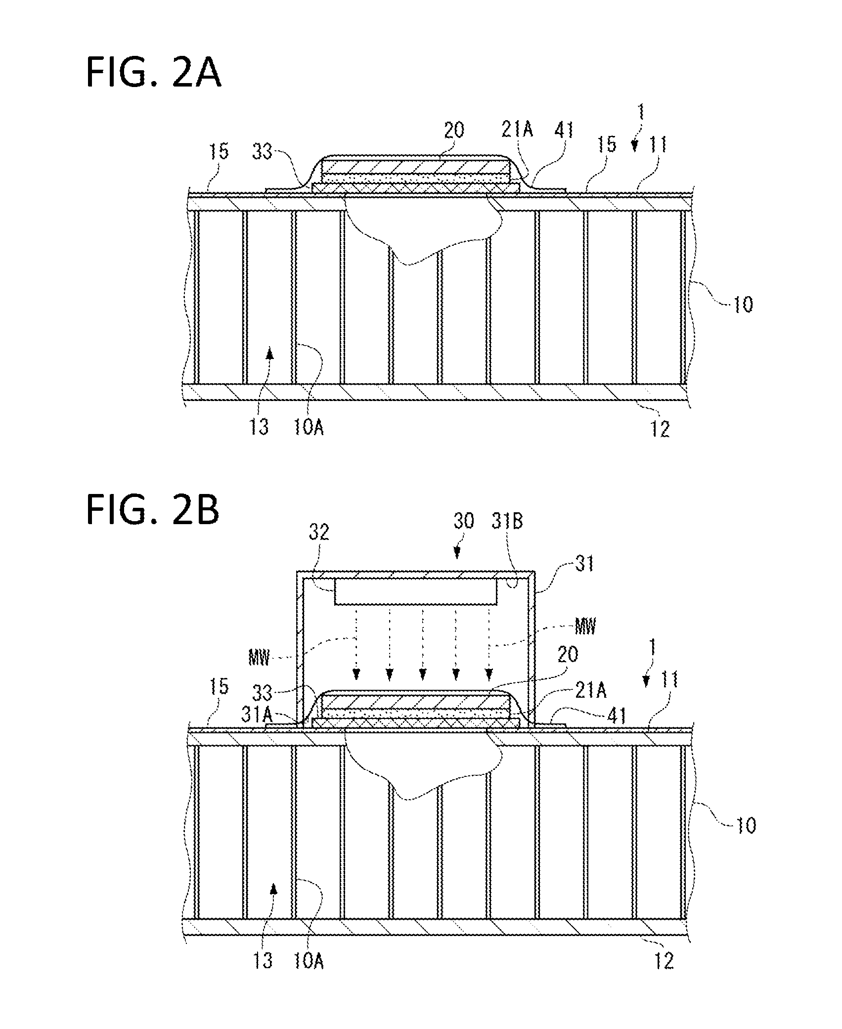
[0112]In the repair method of the second embodiment, a moisture releasing step is performed, which releases moisture accumulated inside the core 10 of the outer panel 1 of a honeycomb core sandwich panel to the outside by irradiating it with the microwaves MW.

[0113]For this purpose, the microwave irradiator 30 is disposed to the outer skin 12 of the outer panel 1, and the shield member 33 is disposed to the outer skin 11 opposite to the outer skin 12 at a position facing the microwave irradiator 30.

[0114]In the moisture releasing step, the microwave irradiator 30 is operated to radiate the microwaves MW from the oscillator 32 to the outer panel 1. Then, the microwaves MW are also radiated to the inside of the co...


PUM

PropertyMeasurementUnit
oscillation frequencyaaaaaaaaaa
electromagneticaaaaaaaaaa
structureaaaaaaaaaa

Abstract

The present invention sufficiently heats a repairing material while preventing change in quality of a base material provided with the repairing material so as to securely bond the repairing material to a repair target portion. The repair method of the present invention, in order to repair a repair target portion 14 existing in an outer panel 1, includes a repairing material disposing step of disposing a repairing patch 20 and an adhesive 21A to the repair target portion 14; and a heating-hardening step of heating and hardening the adhesive 21A by irradiating it with electromagnetic waves.

Description

BACKGROUND OF THE INVENTION[0001]1. Field of the Invention[0002]The present invention relates to a method of repairing a repair target portion existing in a repair target, and a repair apparatus.[0003]2. Description of the Related Art[0004]An outer panel (skin) forming an outer surface of a fuselage and a wing of an aircraft requires repairing if the outer panel is damaged by a lightning strike or flying objects such as hailstones. As a repairing material for use in such repairing, a composite material, such as fiber reinforced plastic (FRP), is used.[0005]In order to heat and harden the repairing material so as to bond this repairing material to the repair target portion, a heater mat is used, as shown in Japanese Patent Laid-Open No. 2009-208301. The heater mat is placed on the repairing material disposed to the repair target portion. A heat gun or an oven may also be used for heating the repairing material.[0006]An external heat source, such as a heater mat, is used for heating t...

Claims


Application Information

Patent Timeline
Patent Type & Authority Applications(United States)
IPC IPC(8): B29C73/10B29C71/04
CPCB29C71/04B29C73/10B29C73/12B29C73/30B29C73/34B29C2035/0855
Inventor ARIKAWA, KIWAMUSUHARA, MASAYOSHIISEKI, HIROYUKIMUTO, SHUHEI
Owner MITSUBISHI AIRCRAFT
Learn More