Resonator element, resonator, oscillator, electronic apparatus, and moving object

a resonator and element technology, applied in the direction of oscillator, piezoelectric/electrostrictive/magnetostrictive device, oscillator generator, etc., can solve the problems of deterioration of q value, ci value, q value deterioration, etc., and achieve the effect of improving the sensitivity and sensitivity of the q valu

Active Publication Date: 2014-10-02
SEIKO EPSON CORP
View PDF9 Cites 18 Cited by
  • Summary
  • Abstract
  • Description
  • Claims
  • Application Information

AI Technical Summary

Benefits of technology

[0009]An advantage of the invention is to provide a resonator element, a resonator, an oscillator, an electronic apparatus, and a moving object each capable of sufficiently separating the resonant frequency in the X-common mode from the resonant frequency in the main mode in the miniaturization.
[0010]The invention can be implemented as the following application examples.

Problems solved by technology

Therefore, in the resonator of Document 1, the vibration leakage increases when vibrating in the main mode, and thus, the deterioration of the Q value and the deterioration of the CI value due to the deterioration of the Q value are caused problematically.
However, in the miniaturization, it is insufficient to reduce the degree of the approximation of the resonant frequency in the X-common mode to the resonant frequency in the main mode.

Method used


Image

  • Resonator element, resonator, oscillator, electronic apparatus, and moving object
  • Resonator element, resonator, oscillator, electronic apparatus, and moving object
  • Resonator element, resonator, oscillator, electronic apparatus, and moving object

Examples


first embodiment

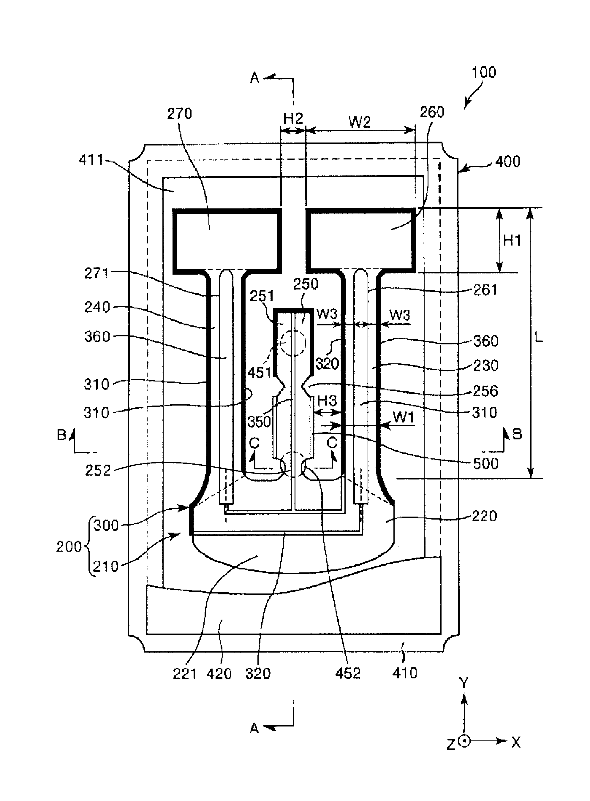
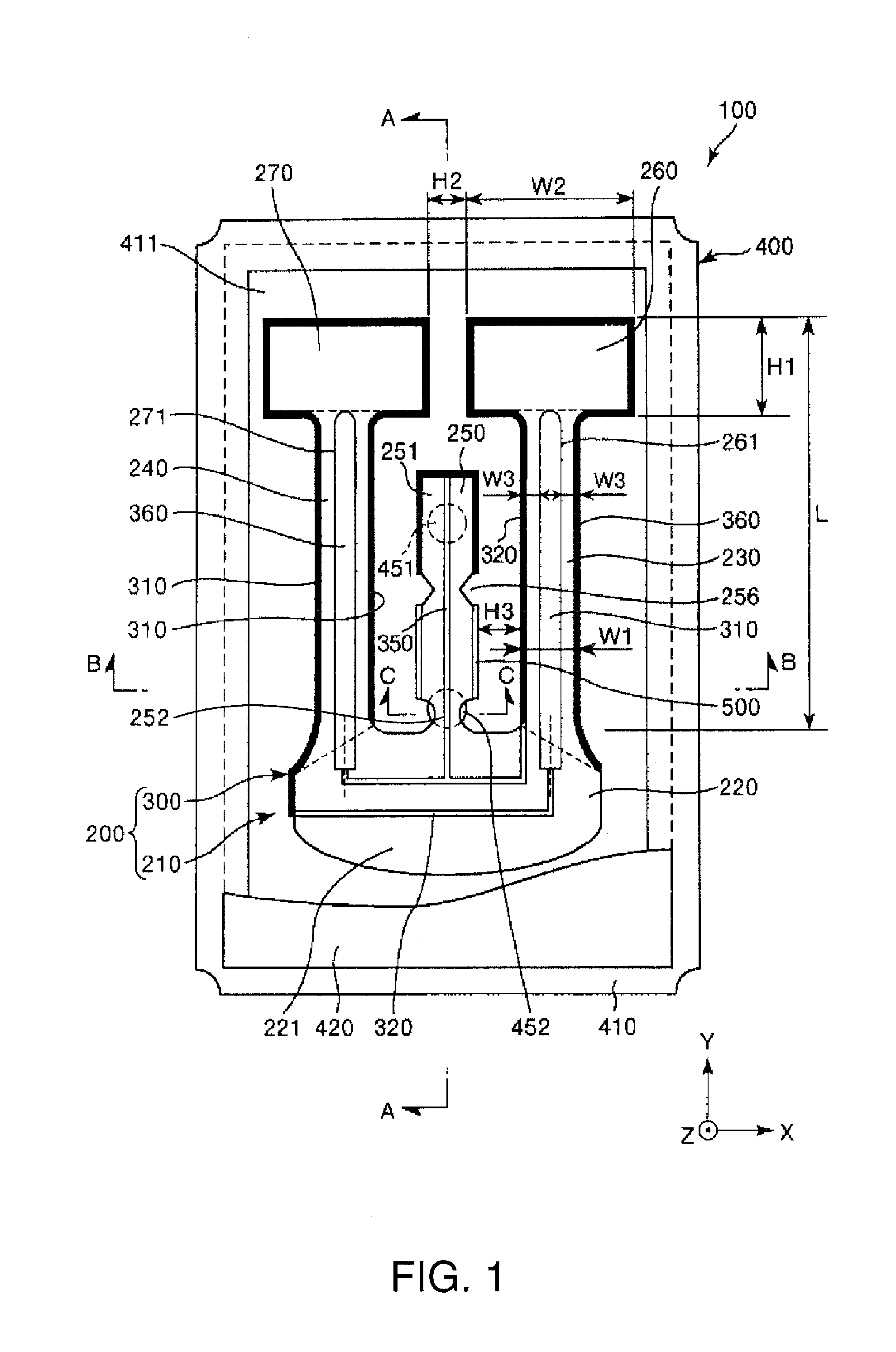
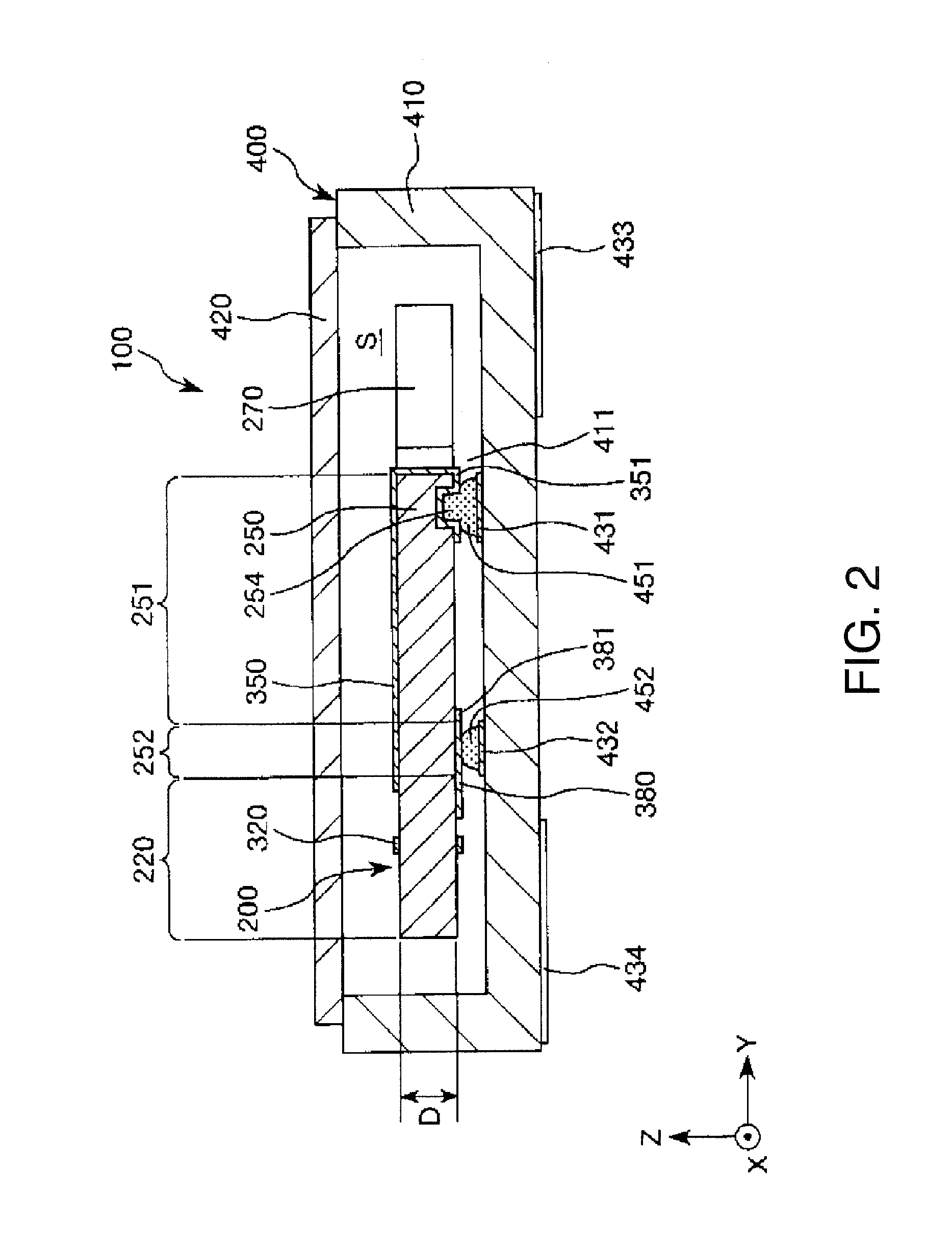
[0066]FIG. 1 is a plan view showing a resonator according to a first embodiment of the invention, FIG. 2 is a cross-sectional view along the A-A line in FIG. 1, FIGS. 3A and 3B are plan views for explaining the principle of reduction in vibration leakage, FIG. 4 is a cross-sectional view along the B-B line in FIG. 1, FIG. 5 is a cross-sectional view of a vibrating arm for explaining heat transfer in a flexural vibration, FIG. 6 is a graph showing a relationship between Q-value and f / fm, FIG. 7 is a cross-sectional view along the C-C line in FIG. 1, FIG. 8 is a plan view showing a positional relationship between a width-decreasing portion and an electrically-conductive adhesive, FIGS. 9A and 9B are plan views showing the resonator element shown in FIG. 1, wherein FIG. 9A is a top view, and FIG. 9B is a bottom view (a transparent view), and FIGS. 10A through 10C are cross-sectional views for explaining a method of manufacturing the resonator element shown in FIG. 1. It should be noted...

second embodiment

[0146]Then, a resonator according to a second embodiment of the invention will be explained.

[0147]FIGS. 11A and 11B are plan views showing a resonator element according to the second embodiment of the invention, wherein FIG. 11A is a top view, and FIG. 11B is a bottom view (a transparent view).

[0148]Hereinafter, the resonator according to the second embodiment of the invention will be described with reference to these drawings with a focus mainly on the differences from the embodiment described above, and the explanations regarding similar matters will be omitted.

[0149]The second embodiment is substantially the same as the first embodiment except the point that the configuration of the support arm is different.

[0150]In the resonator element 200A shown in FIGS. 11A and 11B, the pair of notches 256 are eliminated. However, in the exposure process described above, by performing the oblique exposure on a part of each of the side surfaces of the support arm 250, specifically a part midwa...

third embodiment

[0152]Then, a resonator according to a third embodiment of the invention will be explained.

[0153]FIGS. 12A and 12B are plan views showing a resonator element according to the third embodiment of the invention, wherein FIG. 12A is a top view, and FIG. 12B is a bottom view (a transparent view). FIG. 13 is a cross-sectional view along the D-D line in FIG. 12A.

[0154]Hereinafter, the resonator according to the third embodiment of the invention will be described with reference to these drawings with a focus mainly on the differences from the embodiments described above, and the explanations regarding similar matters will be omitted.

[0155]The third embodiment is substantially the same as the first embodiment except the point that the configuration of the support arm is different.

[0156]The resonator element 200B shown in FIGS. 12A, 12B, and 13 is provided with a groove 255 disposed midway in the longitudinal direction of the tip portion 251. The groove 255 is located between the contact are...


PUM


Abstract

A resonator includes a resonator element including a base section, vibrating arms extending from the base section, and a support arm disposed between the vibrating arms, a package adapted to support the resonator element, and electrically-conductive adhesives adapted to fix the support arm to the package, the support arm includes a tip portion and a width-decreasing portion having a width smaller than the width of the tip portion, and the electrically-conductive adhesive has contact with at least a part of the width-decreasing portion in a planar view.

Description

BACKGROUND[0001]1. Technical Field[0002]The present invention relates to a resonator element, a resonator, an oscillator, an electronic apparatus, and a moving object.[0003]2. Related Art[0004]In the past, there has been known a quartz crystal oscillator having a resonator element housed in a package (see, e.g., JP-A-2002-141770 (Document 1)).[0005]The resonator of Document 1 has a base section, a pair of vibrating arms each having a widened portion disposed in one end portion, a resonator element disposed between the pair of vibrating arms, and having a support arm extending from the base section, and a package housing the resonator element. Further, the resonator element is fixed to the package via a pair of electrically-conductive adhesives. The pair of electrically-conductive adhesives are disposed on one surface of the support arm in the thickness direction. According to such a configuration as described above, the resonator can be made relatively small.[0006]However, according...

Claims


Application Information

Patent Timeline
Patent Type & Authority Applications(United States)
IPC IPC(8): H03H9/215H01L41/09H03B28/00
CPCH03H9/215H01L41/09H03B28/00H03B5/32H03H9/1021
Inventor YAMADA, AKINORI
Owner SEIKO EPSON CORP
Why Eureka
Try Eureka