Pulse transformer

Active Publication Date: 2014-10-02
TDK CORPARATION
View PDF6 Cites 27 Cited by
  • Summary
  • Abstract
  • Description
  • Claims
  • Application Information

AI Technical Summary

Benefits of technology

[0019]It is preferable in the present invention that the first center tap includes first and second center tap terminal electrodes provided on the second flange, the second center tap includes third and fourth center tap terminal electrodes provided on the first flange, the one end of the second wire is connected to the first center tap terminal electrode, the other end of the first wire is connected to the second center tap terminal electrode, the other end of the third wire is connected to the third center tap terminal electrode, the one end of the fourth wire is connected to the fourth center tap terminal electrode, a front end of the second center tap terminal electrode positioned near the inner side surface of the second flange is set back toward the outer side surface of the second flange, and a front end of the fourth terminal electrode positioned near the inner side surface of the first flange is set back toward the outer side surface of the first flange. With this configuration, in a pulse transformer of a four-terminal-pair structure, it is possible to avoid the wire lead section from contacting a different terminal fitting from its connection terminal electrode. This allows a pulse transformer having high connection reliability to be provided and allows facilitation of lead-out of the wire and connection of the wire to the terminal electrode.
[0020]It is preferable in the present invention that the first center tap includes first and second center tap regions provided in a single terminal electrode, that the second center tap includes third and fourth center tap regions provided in a single terminal electrode, the one end of the second wire is connected to the first center tap region, the other end of the first wire is connected to the second center tap region, the other end of the third wire is connected to the third center tap region, the one end of the fourth wire is connected to the four

Problems solved by technology

However, the above-described conventional pulse transformer has a problem in that the lead section of one wire that crosses the other may also contact a different terminal electrode from its connection target terminal

Method used


Image

  • Pulse transformer
  • Pulse transformer
  • Pulse transformer

Examples


first embodiment

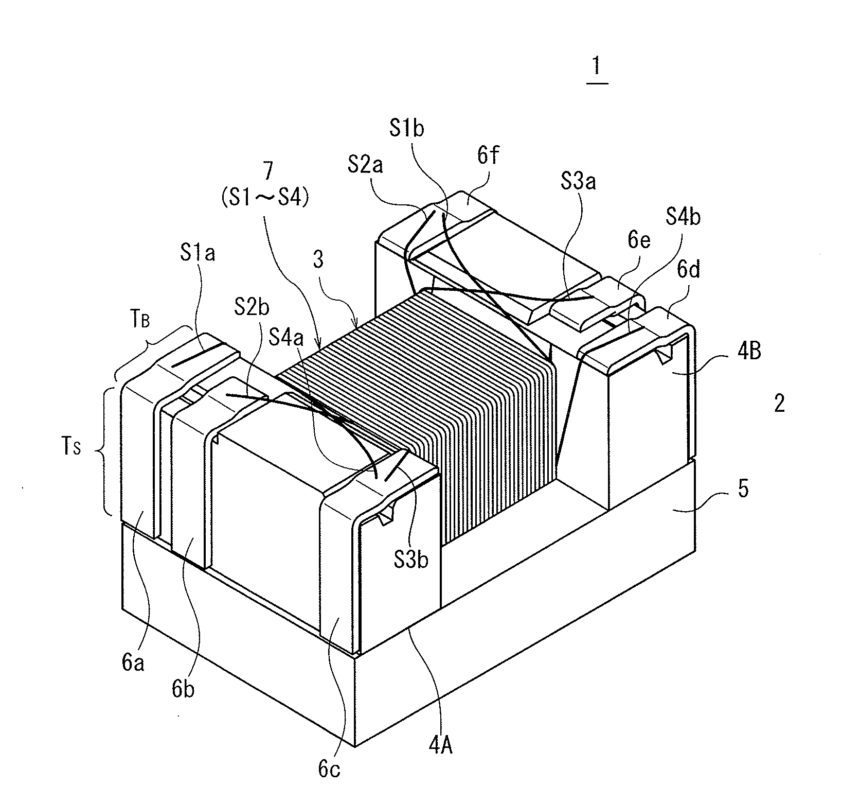
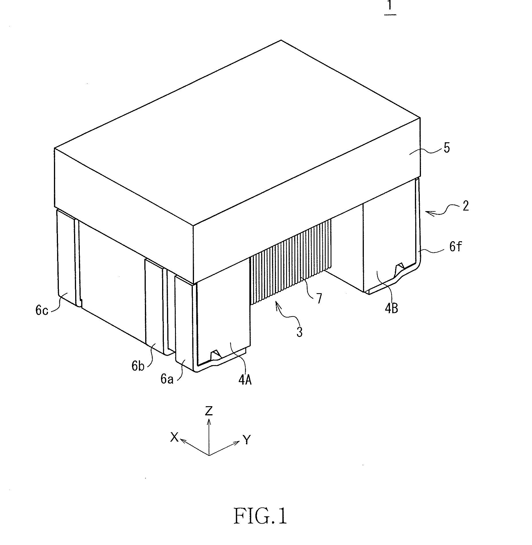
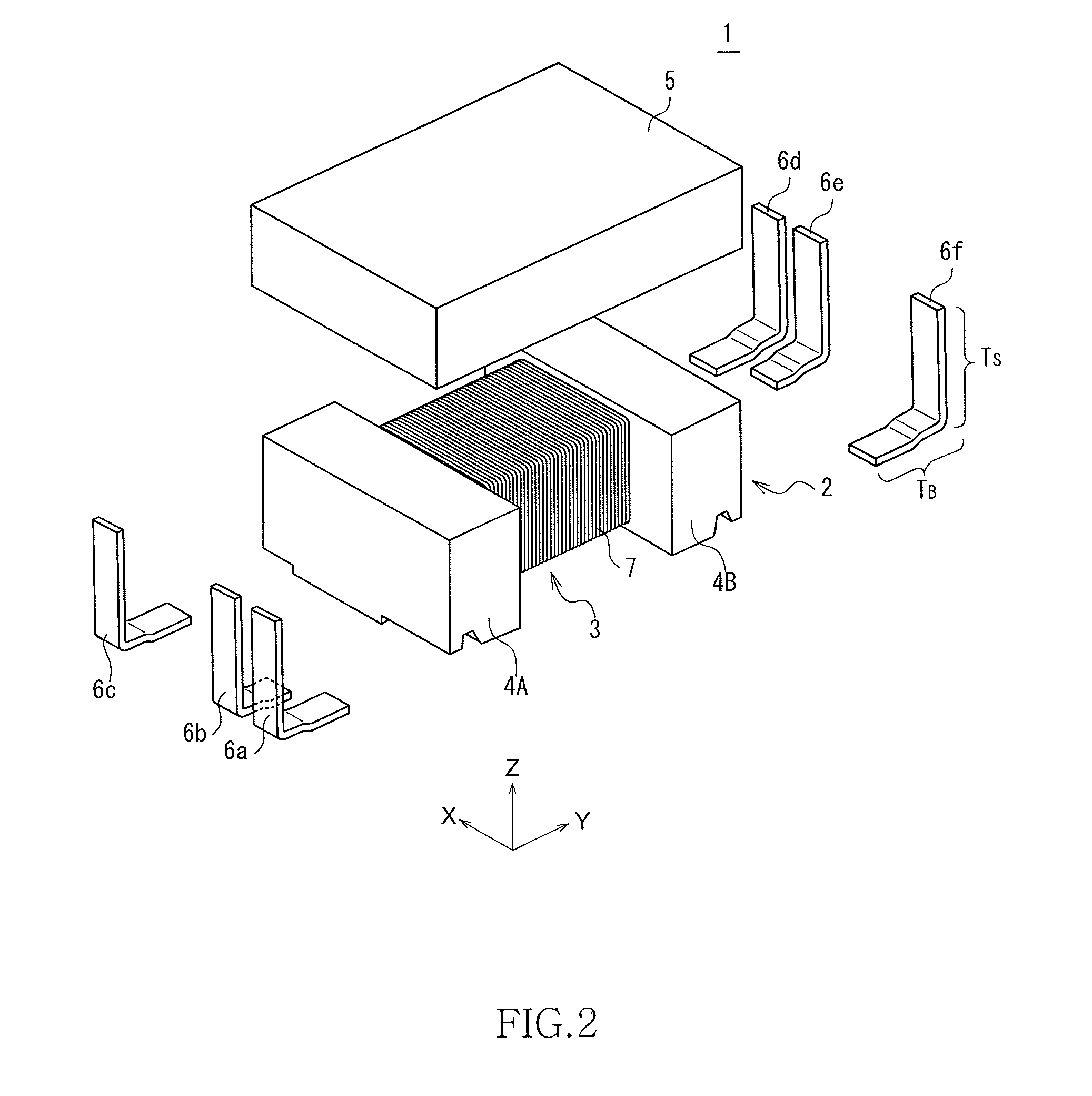
[0039]FIG. 1 is a schematic perspective view illustrating an outer appearance of a pulse transformer 1 according to the present invention. FIG. 2 is an exploded perspective view of the pulse transformer 1 according to the present embodiment, and FIG. 3 is a schematic perspective view of the pulse transformer 1 set with the top and bottom thereof reversed and viewed from the bottom side.

[0040]As illustrated in FIGS. 1 to 3, the pulse transformer 1 according to the present embodiment includes a drum core 2, a plate core 5, six terminal fittings 6a to 6f, and a coil 7 having wires wound around the drum core 2. Although not especially limited, the pulse transformer 1 has a size of about 4.5 mm (X-direction)×about 3.2 mm (Y-direction)×about 2.9 mm (Z-direction).

[0041]The drum core 2 is formed of a magnetic material such as an Ni—Zn-based ferrite and includes a winding core 3 around which the coil 7 is wound and a pair of flanges 4A and 4B disposed at both ends of the winding core 3 in th...

second embodiment

[0065]FIG. 6 is an exploded perspective view of a pulse transformer 8 according to the present invention, and FIG. 7 is a schematic perspective view of the pulse transformer 8 set with the top and bottom thereof reversed and viewed from the bottom side.

[0066]As illustrated in FIGS. 6 and 7, the terminal fitting 6c is divided into two terminal fittings 6c1 and 6c2, and terminal fitting 6f is divided into two center tap terminal fittings 6f1 and 6f2. That is, four terminal fittings are fixed to each of the pair of flanges 4A and 4B. In this case, the other end S3b of the wire S3 is connected to the terminal fitting 6c1 (or 6c2), the one end S4a of the wire S4 is connected to the terminal fitting 6c2 (or 6c1), one end S2a of the wire S2 is connected to the terminal fitting 6f1 (or 6f2), and the other end S1b of the wire S1 is connected to the terminal fitting 6f2 (or 6f1). Then, the terminal fittings 6f1 and 6f2 are short-circuited to each other through a wiring pattern (land) on a pri...

third embodiment

[0081]FIG. 10 is a schematic plan view illustrating a structure of a pulse transformer 9 according to the present invention, and more specifically illustrating a shape of the bottom portion of each terminal fitting provided on the flange.

[0082]As illustrated in FIG. 10, a pulse transformer 9 according to the present embodiment uses, in place of the two terminal fittings 6c1 and 6c2 of the pulse transformer 8 illustrated in FIGS. 6 to 9, one large terminal fitting 6c that covers formation areas of the terminal fittings 6c1 and 6c2 and uses, in place of the two terminal fittings 6f1 and 6f2 of the pulse transformer 8, one large terminal fitting 6f that covers formation areas of the terminal fittings 6f1 and 6f2. In this case, the one end S4a of the wire S4 is connected to an inside area 6ci (or outside area 6co) of the terminal fitting 6c, and the other end S3b of the wire S3 is connected to an outside area 6co (or inside area 6ci) of the terminal fitting 6c. Further, the one end S2a ...


PUM


Abstract

A pulse transformer is provided with a drum core 2 including a winding core 3 and first and second flanges 4A and 4B, and wires S1 to S4 wound around a winding core 3 of the drum core 2. Terminal electrodes 6a and 6b and a center tap 6c are provided on the flange 4A, and terminal electrodes 6d and 6e and a center tap 6f are provided on the flange 4B. Each end of the wires S1 to S4 is connected to a corresponding one of the terminal electrodes P1 and N1, the center tap CT2, the terminal electrodes P2 and N2, and the center tap CT1. A front end of the terminal electrode 6b is setback toward an outer side surface of the flange 4A, and a front end of the terminal electrode 6e is setback toward an outer side surface of the first flange 4B.

Description

BACKGROUND OF THE INVENTION[0001]1. Field of the Invention[0002]The present invention relates to a pulse transformer and, more particularly, to a surface-mount pulse transformer using a drum-type core.[0003]2. Description of Related Art[0004]In recent years, in a circuit component such as a connecter, a pulse transformer is widely used for isolating a differential signal at an input side (primary side) and a differential signal at an output side (secondary side). In order to mount a plurality of pulse transformers on a printed circuit board at high density, it is preferable to use a surface-mount pulse transformer using a drum core (see Japanese Patent Application Laid-Open Nos. 2009-302321 and 2010-109267).[0005]A pulse transformer described in the Japanese Patent Application Laid-Open No. 2010-109267 has a configuration in which primary-side terminal electrodes and a secondary-side center tap are formed in one flange of a drum core, and secondary-side terminal electrodes and a pri...

Claims


Application Information

Patent Timeline
IPC IPC(8): H01F27/29
CPCH01F27/292H01F3/10H01F27/2828
Inventor TAKAGI, NOBUOTSUCHIDA, SETUMIKOGAMI, TASUKU
Owner TDK CORPARATION
Why Eureka
Try Eureka