Transmitting device and transmitting method

Active Publication Date: 2014-10-02
PANASONIC INTELLECTUAL PROPERTY CORP OF AMERICA
View PDF1 Cites 61 Cited by
  • Summary
  • Abstract
  • Description
  • Claims
  • Application Information

AI Technical Summary

Benefits of technology

[0015]According to the present disclosure, the influence by the interference to another user terminal belonging to the other cell such as

Problems solved by technology

However, conventionally, in the case that the DMRSs are transmitted among the plurality of cells using different mapping patterns, sometimes the

Method used


Image

  • Transmitting device and transmitting method
  • Transmitting device and transmitting method
  • Transmitting device and transmitting method

Examples


Example

First Exemplary Embodiment

Outline of Communication System

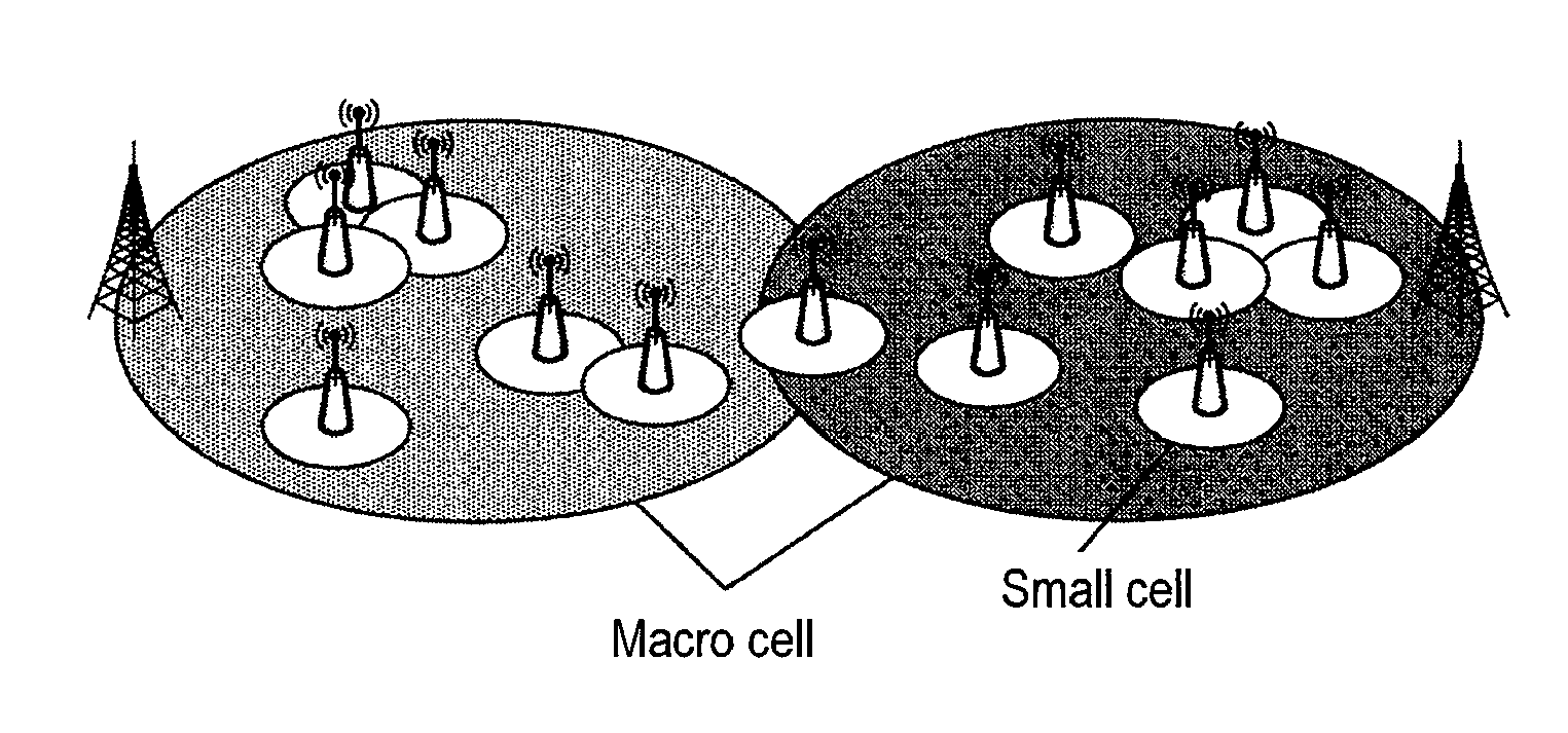
[0063]FIG. 7 illustrates a communication system according to a first exemplary embodiment. The communication system in FIG. 7 consists of base station 100 and one or a plurality of user terminals 200 in a cell. In FIG. 7, base station 100 may be a macro cell base station or a small cell base station. The communication system may be a HetNet system including both the macro cell base station and the small cell base station or a CoMP (Coordinated multipoint) system in which a plurality of base stations communicate with the user terminal in a coordinated manner. The macro cell and the small cell may be operated at different frequency bands or at the same frequency band.

[0064][Configuration of Base Station 100]

[0065]FIG. 8 is a block diagram illustrating a main part of base station 100.

[0066]Base station 100 in FIG. 8 includes control signal generating section 11, transmitting section 12, receiving section 13, channel estimating se...

Example

Second Exemplary Embodiment

Outline of Communication System

[0173]Similarly to the first exemplary embodiment (see FIG. 7), a communication system according to a second exemplary embodiment consists of base station 100 and one or a plurality of user terminals 200.

[0174]In the second exemplary embodiment, the power (power density) offset is added to the additional data resource, and the MCS level is set based on a criterion different from the data except the additional data.

[0175][Configuration of Base Station 100]

[0176]Using the higher layer, control section 101 of base station 100 previously notifies user terminal 200 of the MCS level that is used in the additional data resource during the use of the reduced DMRS. The MCS level used in the additional data resource may be set according to the reduced DMRS pattern or the allocated bandwidth. For example, control section 101 sets the MCS level to the higher value as the number of DMRS resources of the reduced DMRS pattern decreases, whe...

Example

[0190]In embodiment 2, the MCS level of the additional data resource can semi-statically be fixed while the MCS level of the resource except the additional data resource is dynamically changed in each PUSCH allocation. Therefore, the securement of the reception quality and the implementation of the dynamic and variable data rate are facilitated. That is, the MCS level can properly be selected according to the state of user terminal 200.

[0191][Variation 1]

[0192]In variation 1, user terminal 200 (control section 205) controls the MCS level of the additional data resource by adding the offset to the MCS level of the resource except the additional data resource. The notification of the offset of the MCS level may be made through the higher layer.

[0193]Similarly to FIG. 17, FIG. 18 illustrates the transmission power (see FIG. 18A) and the MCS level (see FIG. 18B) in the case that the power offset X [dBm] is added to the additional data resource using reduced DMRS pattern (1).

[0194]User t...


PUM


Abstract

For use of a second mapping pattern in which a part of a resource on which a DMRS (Demodulation Reference Signal) is to be mapped is replaced with a data resource in a first mapping pattern of the DMRS, control section (23) adds an offset to a transmission power or a transmission power density of first data mapped in a remaining resource other than a data resource to control a transmission power or a transmission power density of second data mapped to the part of a resource. Transmitting section (25) transmits a signal including the first data, the second data, and the DMRS.

Description

BACKGROUND OF THE INVENTION[0001]1. Field of the Invention[0002]The present disclosure relates to a transmitting device and a transmitting method.[0003]2. Description of the Related Art[0004]In LTE (Long Term Evolution) Rel.8 (Release 8) developed by 3GPP (3rd Generation Partnership Project Radio Access Network), SC-FDMA (single-carrier frequency-division multiple-access) is adopted as an uplink communication system (for example, see 3GPP TS 36.211, “Evolved Universal Terrestrial Radio Access (E-UTRA); Physical channels and modulation,” v.11.1.0, 3GPP TS 36.212, “Evolved Universal Terrestrial Radio Access (E-UTRA); Multiplexing and channel coding,” v.11.1.0, and 3GPP TS 36.213, “Evolved Universal Terrestrial Radio Access (E-UTRA); Physical layer procedures,” v.11.1.0). The SC-FDMA has a smaller PAPR (Peak-to-Average Power Ratio) and higher power usage efficiency at a user terminal, (UE: User Equipment).[0005]In an uplink of the LTE, a data signal is transmitted in units of subframes...

Claims


Application Information

Patent Timeline
IPC IPC(8): H04L5/00H04W52/24
CPCH04L5/0073H04W52/244H04L5/0051H04L5/0044H04L1/0003
Inventor TAKEDA, KAZUKIHOSHINO, MASAYUKIGOLITSCHEK EDLER VON ELBWART, ALEXANDER
Owner PANASONIC INTELLECTUAL PROPERTY CORP OF AMERICA
Why Eureka
Try Eureka