X-ray generation

a technology of x-ray and x-ray, which is applied in the field of x-ray generation, can solve the problems of large facilities, high cost, and not readily available to everyone, and achieve the effects of increasing the resultant x-ray flux, facilitating selection, and facilitating the use of x-rays

Active Publication Date: 2014-10-09
OXFORD UNIV INNOVATION LTD
View PDF2 Cites 9 Cited by
  • Summary
  • Abstract
  • Description
  • Claims
  • Application Information

AI Technical Summary

Benefits of technology

[0037]The applicants have further realized that turning the electron beam through an angle up to 180° can be particularly beneficial when interacting the accelerated beam with photons to generate x-rays via inverse-Compton scattering. Turning the beam provides an interaction zone where the angle of impact between a photon beam and the electron beam can be more freely selected to tailor the wavelength of the resultant x-rays. It can also be easier to select the direction of the x-rays that are generated so that they can be guided for subsequent use. With a serial arrangement of linear accelerators, on the other hand, it can be difficult to guide a photon beam so as to interact with the straight electron beam and to guide the x-rays away if they are generated close to the beam axis.
[0038]In a preferred set of embodiments means are provided to turn the electron beam substantially through 180° between the first accelerator device and the second dec

Problems solved by technology

While synchrotron light sources such as the one at SLAC and the Diamond light source in the UK can provide researchers with very hard and bright x-rays for experimental studies, such facilities are extremely large, costly to run and not readily available to everyone.
The overall billion dollar-scale cost and huge size of such machines means that they can only be constructed at a national level.
Much of the input power is wasted as the electron beam is dumped following its interaction with the laser beam.
While this source

Method used


Image

  • X-ray generation
  • X-ray generation
  • X-ray generation

Examples


Embodiment Construction

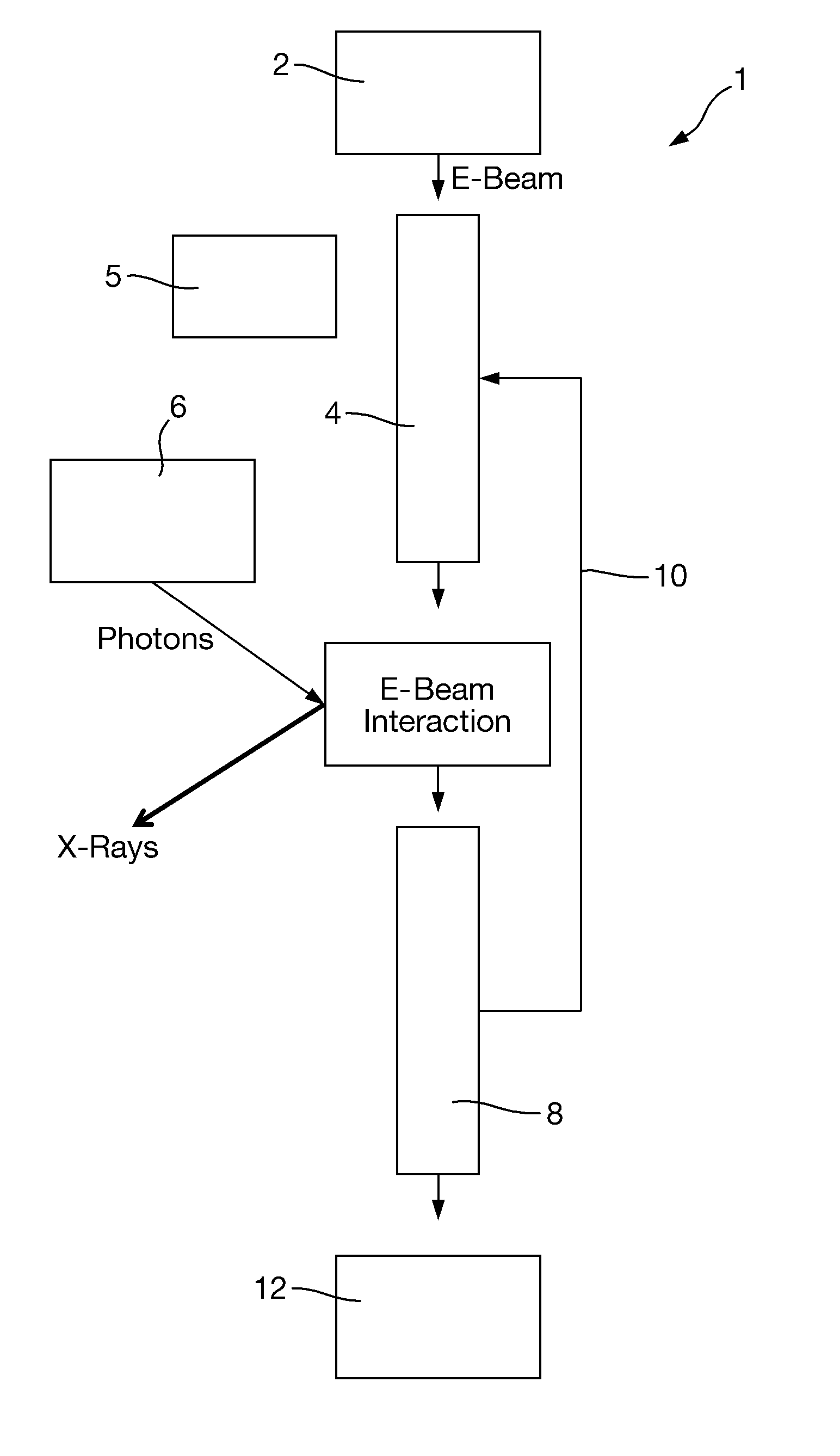
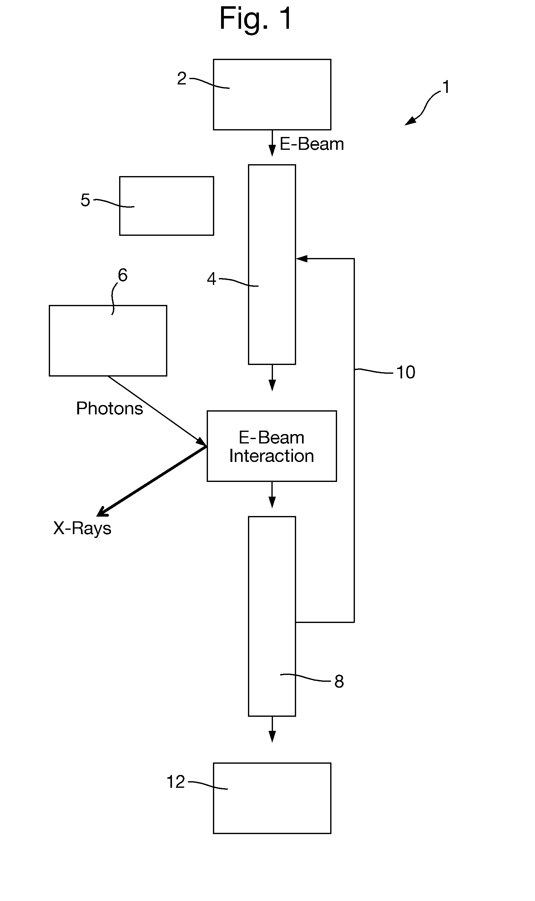
[0054]There is seen from FIG. 1 the basic components of an x-ray generating apparatus 1 depicted in the form of a flow diagram (i.e. not representative of physical layout). An electron beam is generated by an electron gun 2, typically a radiofrequency (RF) photoinjector comprising a RF power supply, a laser source and a photocathode located in a RF cavity to produce bunches of electrons when photons from the laser impact on the photocathode. Such electron guns are well known and will not be described in further detail here. The electron beam (e-beam) generated by the gun 1 may be at an initial energy Emin e.g. around 1 MeV. The electron beam enters a first linear device 4 that is arranged to accelerate the beam up to an interaction energy Emax of about 20 MeV. The accelerator 4 includes a plurality of RF accelerating cavities to which an alternating RF electric field is applied. An RF power supply (not shown) may input around 10 kW of power to drive the acceleration process.

[0055]Th...


PUM


Abstract

An apparatus for generating x-rays includes an electron beam generator and a first device arranged to apply an RF electric field to accelerate the electron beam from the generator. A photon source is arranged to provide photons to a zone to interact with the electron beam from the first device so as to generate x-rays via inverse-Compton scattering. A second device is arranged to apply an RF electric field to decelerate the electron beam after it has interacted. The first and second devices are connected by RF energy transmission means arranged to recover RF energy from the decelerated electron beam as it passes through the second device and transfer the recovered RF energy into the first device.

Description

[0001]This application is entitled to the benefit of, and incorporates by reference essential subject matter disclosed in PCT Application No. PCT / GB2012 / 052632 filed on Oct. 24, 2012, which claims priority to Great Britain Application No. 1118556.8 filed Oct. 27, 2011.BACKGROUND OF THE INVENTION[0002]1. Technical Field[0003]The present invention relates to apparatus and methods for accelerating electrons and extracting energy from electron beams or other particle beams, in particular to techniques for generating x-rays.[0004]2. Background Information[0005]X-rays can be generated by accelerating electrons to high speeds. Conventional methods of x-ray generation use a linear particle accelerator to accelerate electrons to energies of several keV or even MeV. A conventional cathode ray tube emits an electron beam that is accelerated towards a target anode where electromagnetic radiation is generated upon impact. Soft x-rays having energies of 0.12 to 12 keV and wavelengths of 10 to 0.1...

Claims


Application Information

Patent Timeline
IPC IPC(8): H01J35/02H05H9/00
CPCH05G2/00H05H9/00H01J35/02H05H7/18
Inventor SERYI, ANDREI
Owner OXFORD UNIV INNOVATION LTD
Why Eureka
Try Eureka