Simulation method for macromolecular material

a macromolecular material and computer simulation technology, applied in the field of computer simulation methods for macromolecular materials and fillers, can solve the problems of high time and cost for experimental measuremen

Active Publication Date: 2014-10-09
SUMITOMO RUBBER IND LTD
View PDF0 Cites 5 Cited by
  • Summary
  • Abstract
  • Description
  • Claims
  • Application Information

AI Technical Summary

Benefits of technology

[0021]Further, when the polymer model is the coarse-grained model, a repulsive force potential between two particle models which can exert a repulsive force between the particle models which increases up to a finite

Problems solved by technology

Accordingly, much time and cost are req

Method used


Image

  • Simulation method for macromolecular material
  • Simulation method for macromolecular material
  • Simulation method for macromolecular material

Examples


example 1

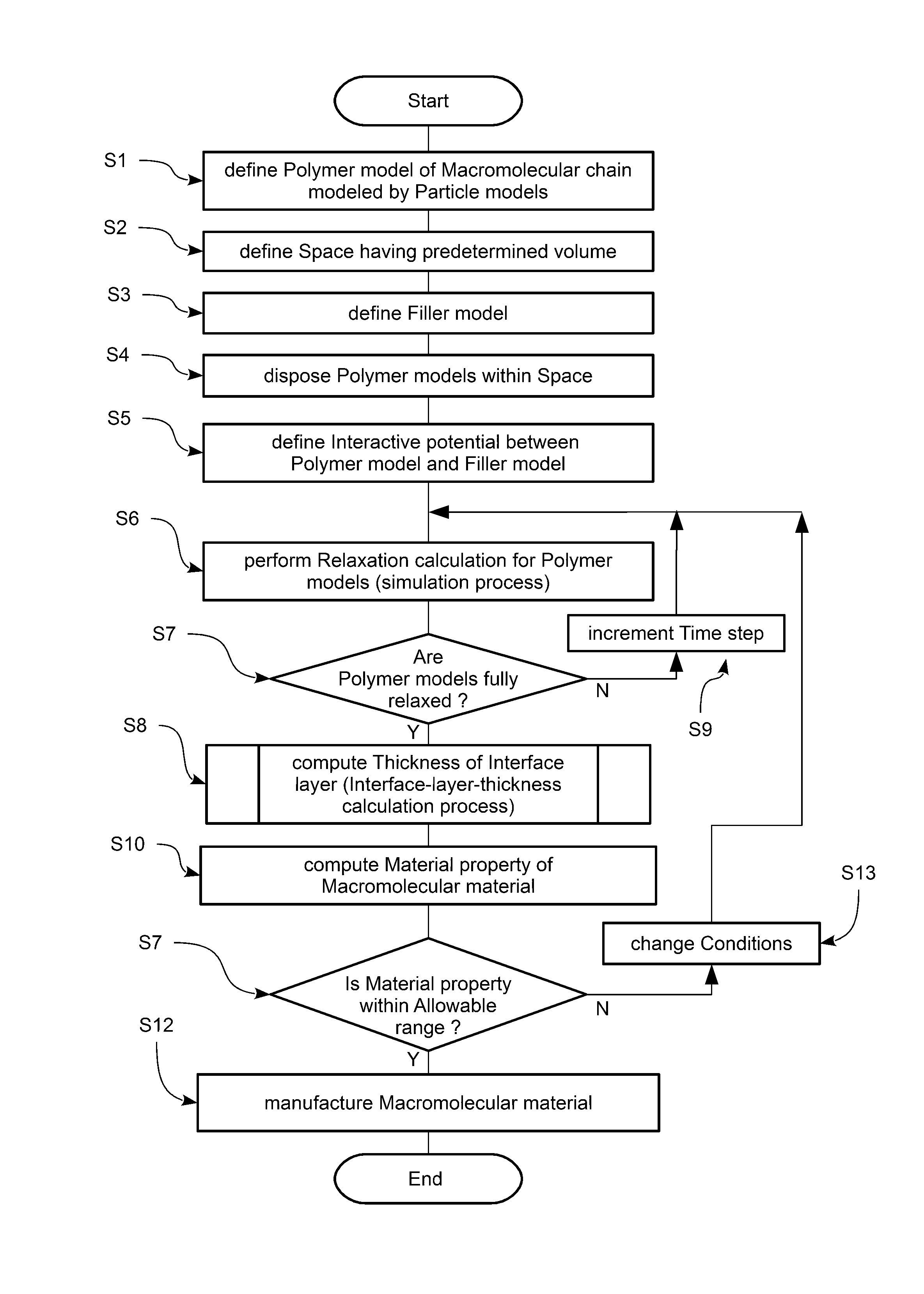
[0298]The repulsive force potential R given by the expression (1) was defined. The number of the particle models 3 in a polymer model was 50. The radius of inertia was 2.89σ. The length L1 of one side of the space 7 was 28.9σ. The number of the polymer models 2 disposed in the space 7 was 300. The computed thickness w1 was 8.67σ. This value well coincides with the measured value.

example 2

[0299]The repulsive force potential R given by the expression (A1) was defined. The number of the particle models 3 in a polymer model was 20. The radius of inertia was 1.35σ. The length L1 of one side of the space 7 was 13.5σ. The number of the polymer models 2 disposed in the space 7 was 500. The computed thickness w1 was 4.05σ. This value also well coincides with the measured value.

[0300]With respect to the second embodiment (all-atom model 3), the thickness w1 of the interface layer was computed according to the procedure as explained above as Example 3.

example 3

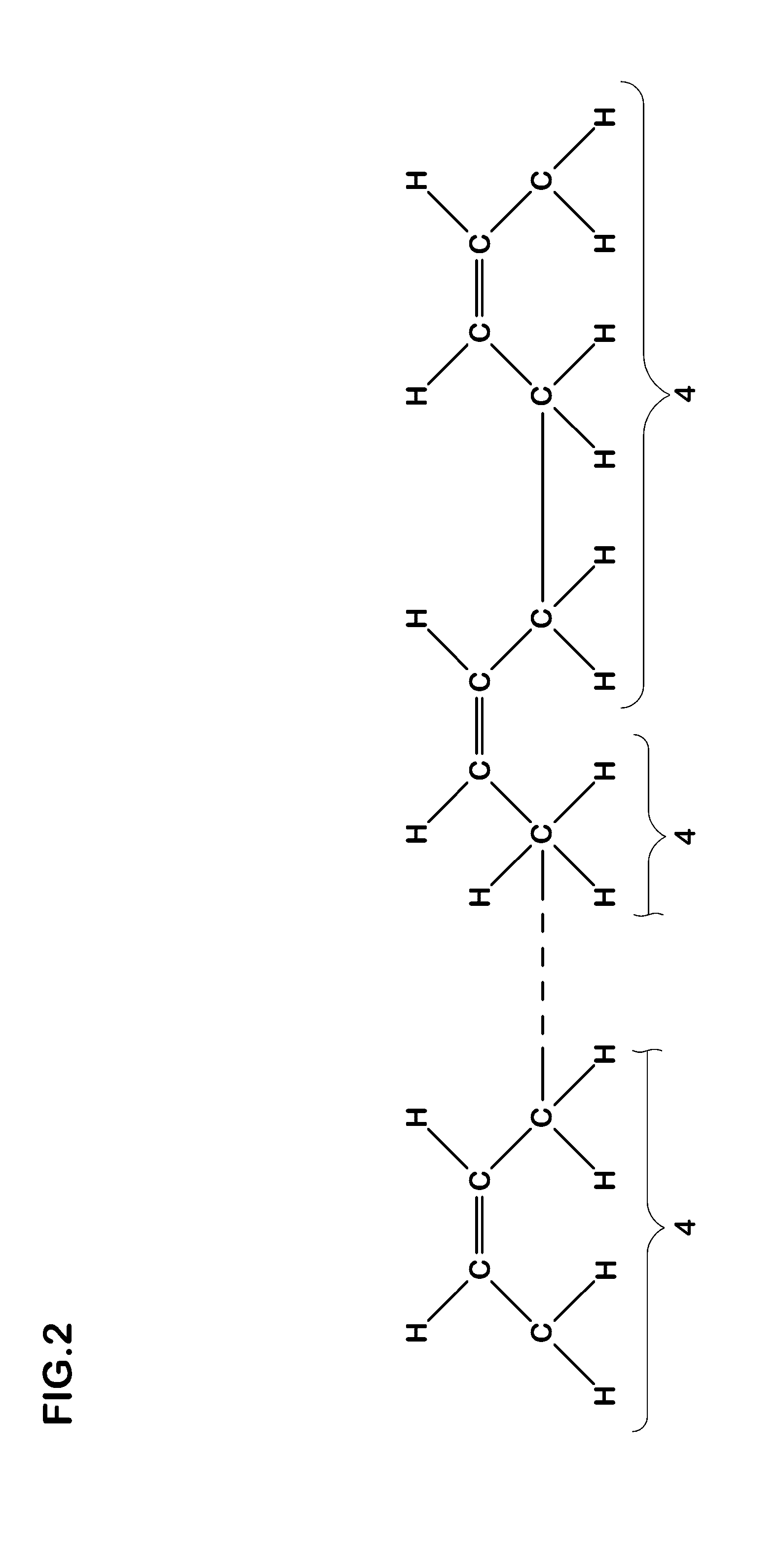
[0301]The macromolecular material was cis-1,4 polybutadiene. The polymerization degree (n) was 10. The radius of inertia was 2.5 Å. The length L1 of one side of the space 7 was 40 Å. The number of the polymer models 2 disposed in the space 7 was 100.

[0302]The computed thickness w1 was 7.5 Å. This value well coincides with the measured value.

[0303]In each example, the computed thickness w1 well coincides with the measured value. Further, in the case of the experimental measurement, it takes several hundred hours to obtain the thickness of the interface layer. But, according to the present invention, it takes only about 1 / 10 to 1 / 20 of that time for the computer of a workstation class to compute the thickness w1.


PUM


Abstract

A computer simulation method for a macromolecular material and filler is disclosed, wherein a polymer model of a macromolecular chain of the macromolecular material and a filler model of the filler are defined; and a molecular dynamics calculation is performed using the filler model and the polymer models disposed in a space in order to compute the thickness of an interface layer between the filler and the macromolecular material. To compute the thickness, the space is partitioned into domains bounded by boundary surfaces; relaxation moduli of the domains are computed; and based on a variation of the relaxation moduli of the domains, the thickness of the interface layer is computed.

Description

BACKGROUND OF THE INVENTION[0001]The present invention relates to a computer simulation method for a macromolecular material and filler, more particularly to a method for computing the thickness of an interface layer formed between the macromolecular material and the filler.[0002]In recent years, in order to develop or design macromolecular materials such as rubber compounds, there have been proposed computer simulation methods in which various conditions such as the structure of the macromolecular material and the blending ratio of filler can be incorporated into the simulation calculation, and thereby it is possible to obtain a material property without experimentally actually producing the macromolecular material with the filler.[0003]In the meantime, when filler is blended into a macromolecular material, as shown in FIG. 10, around the filler particles or aggregation of the filler, there is formed an interface layer (in some cases, called glass layer) having different dynamic pr...

Claims


Application Information

Patent Timeline
IPC IPC(8): G06F19/00
CPCG06F19/701G16C10/00G16C20/30G06F30/15G06F30/20
Inventor UENO, SHINICHI
Owner SUMITOMO RUBBER IND LTD
Why Eureka
Try Eureka