Touch panel

a touch panel and touch technology, applied in the field of touch panels, can solve the problems of many difficulties in implementation of hybrid touch panels, significant increase in the overall size of devices, and inevitably occur, so as to improve the visibility of the touch panel, simplify the process, and reduce the thickness of the touch panel

Inactive Publication Date: 2014-10-16
LG INNOTEK CO LTD
View PDF3 Cites 45 Cited by
  • Summary
  • Abstract
  • Description
  • Claims
  • Application Information

AI Technical Summary

Benefits of technology

[0009]In the touch panel according to the embodiment, the first and second electrodes can be placed on mutually different surfaces of the substrate. Thus, an additional insulation layer for insulating the first and second electrodes from each other can be omitted.
[0010]Further, the touch panel includes the intermediate layer between the first and second substrates. Since the first and second substrates can be combined with each other through the intermediate layer, the process can be simplified. In addition, since an additional adhesive layer can be omitted, a thickness of the touch panel can be reduced.
[0011]The intermediate layer may have the light transmittance of 80% or more in the visible ray band, so that the visibility of the touch panel can be improved.
[0012]The intermediate layer may have a refractive index in the range of 1.30 to 1.52. Thus, when the touch panel of the embodiment is combined with a display device, the touch panel having a superior display performance can be achieved. Further, the light transmittance of the touch panel as well as an anti-reflection function of the touch panel can be improved.
[0013]The intermediate layer may have a color, so that a color difference from the pressure detecting electrode or the position detecting electrode can be compensated. That is, the haze of the touch panel can be compensated. Thus, the color difference of the touch panel can be removed and a high resolution can be provided, so that the visibility can be improved.
[0014]Further, the intermediate layer can insulate the pressure detecting electrode from the position detecting electrode, so that an electrical short can be prevented.

Problems solved by technology

However, if the resistive and capacitive touch panels are integrated into one hybrid touch panel without taking any specific measures into consideration, a serious problem, such as a significant increase in an overall size of a device, occurs inevitably.
Thus, although there are various demands of the user, many difficulties are present in implementation of the hybrid touch panel.

Method used


Image

  • Touch panel
  • Touch panel
  • Touch panel

Examples


first embodiment

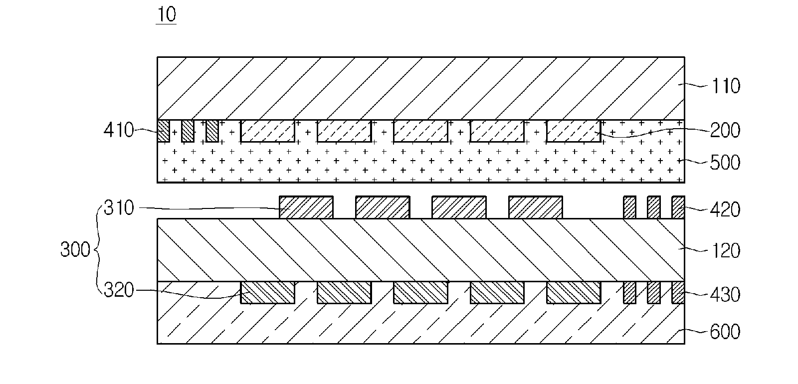
[0028]First, a touch panel will be described with reference to FIG. 1. FIG. 1 is a sectional view showing a touch panel according to the

[0029]Referring to FIG. 1, the touch panel 10 according to the first embodiment includes a first substrate 110, a pressure detecting electrode 200, a second substrate 120, a position detecting electrode 300 and an intermediate layer 500.

[0030]The first substrate 110 may be placed at the most upper portion of the touch panel 10.

[0031]The first substrate 110 may be transparent. The first substrate 110 may be a glass substrate including alkali glass such as soda glass or silicon acid boron glass, alkali-free glass, or chemical strengthening glass. The first substrate 110 may include a polyester film, such as transparent polyethyleneterephthalate or polyethylenenaphthalate (PEN), a polyimide film having thermal resistance and transparency, or a composite polymer having transparent characteristic such as polymethylmethacrylate or polycarbonate.

[0032]A pr...

second embodiment

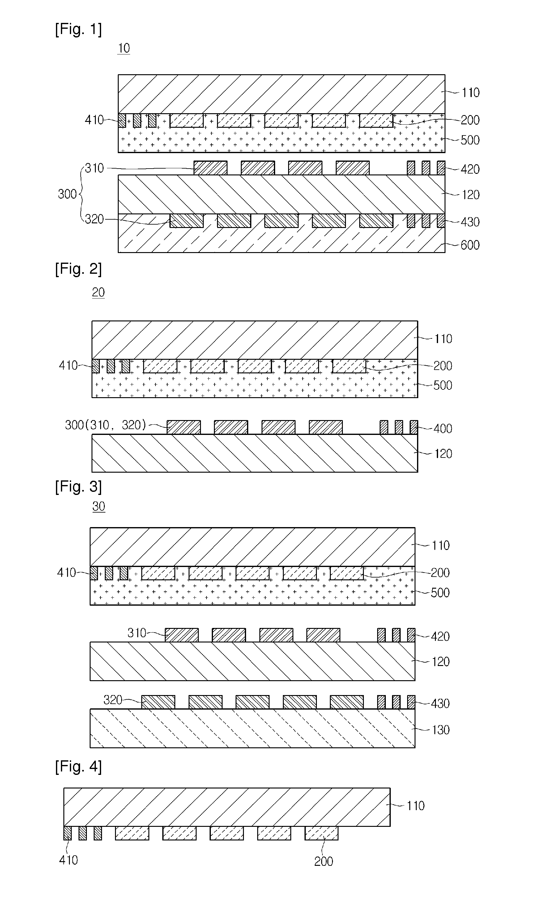
[0068]FIG. 2 is a sectional view showing the touch panel according to the

[0069]Referring to FIG. 2, in the touch panel 20 according to the second embodiment, the position detecting electrode 300 may be placed only on one surface of the second substrate 120. That is, the first and second electrodes 310 and 320 of the position detecting electrode 300 may be placed on the surface of the second substrate 120, so that the thickness of the touch panel may be decreased. Further, the wire 400 for electrically connecting the position detecting electrode 300 may be placed on one surface of the second substrate 120.

[0070]Although not shown in the drawings, an insulation layer may be further placed at a portion in which the first and second electrodes 310 and 320 are overlapped, thereby preventing an electrical short.

third embodiment

[0071]Next, a touch panel will be described with reference to FIG. 3,

[0072]FIG. 3 is a sectional view showing the touch panel according to the third embodiment.

[0073]Referring to FIG. 3, the touch panel 30 according to the third embodiment further includes a third substrate 130 placed below the second substrate 120. The position detecting electrode 300 may be placed on the second and third substrates 120 and 130. However, the embodiment is not limited thereto. The second electrode 320 may be placed on the second substrate 120 and the first electrode 310 may be placed on the third substrate 130.

[0074]The first and second electrodes 310 and 320 may be placed on different substrates, so that touch sensitivity may be improved.

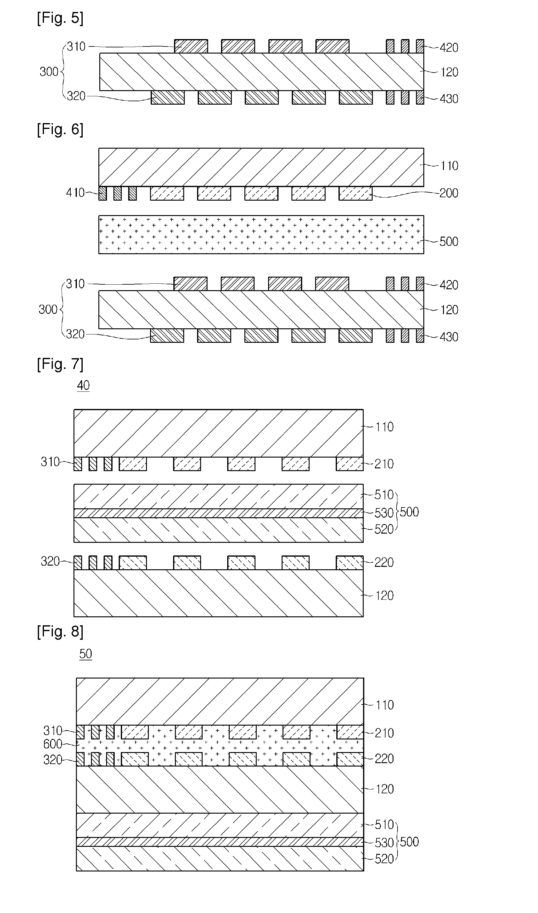
[0075]Hereinafter, a method for fabricating the touch panel according to the embodiment will be described with reference to FIGS. 4 to 6.

[0076]FIGS. 4 to 6 are sectional views illustrating the method for fabricating the touch panel according to the embodiment.

[007...


PUM


Abstract

The touch panel according to the embodiment includes a first substrate and a second substrate spaced apart from each other; a position detecting electrode on at least one of the first and second substrates; a wire connecting the position detecting electrode to a substrate; and an intermediate layer being elastically deformed such that a thickness of the intermediate layer is varied.

Description

CROSS-REFERENCE TO RELATED APPLICATIONS[0001]This application is the U.S. national stage application of International Patent Application No. PCT / KR2012 / 008928, filed Oct. 29, 2012, which claims priority to Korean Application Nos. 10-2011-0110320, filed Oct. 27, 2011, and 10-2011-0127353, filed Nov. 30, 2011, the disclosures of each of which are incorporated herein by reference in their entirety.TECHNICAL FIELD[0002]The disclosure relates to a touch panel.BACKGROUND ART[0003]In general, a touch panel according to the related art is largely classified into a resistive type touch panel and a capacitive type touch panel. The resistive type touch panel includes an upper resistive film and a lower resistive film separated from each other by an insulation spacer, and when a user touches a device, the position is detected through the physical / electrical contact between the upper resistive film and the lower resistive film. In contrast, the capacitive type touch panel includes an X-coordinat...

Claims


Application Information

Patent Timeline
Patent Type & Authority Applications(United States)
IPC IPC(8): G06F3/044G06F3/045
CPCG06F3/045G06F3/044G06F3/0445
Inventor YUN, JI SUNLEE, SANG YOUNGLEE, YONG JINCHAI, KYOUNG HOON
Owner LG INNOTEK CO LTD
Why Eureka
Try Eureka