
Airfoil blades with self-alignment mechanisms for cross-flow turbines

a technology of airfoil blades and cross-flow turbines, which is applied in the direction of rotors, greenhouse gas reduction, vessel construction, etc., can solve the problems of speed increasing, and achieve the effects of reducing efficiency, reducing speed, and reducing speed

Inactive Publication Date: 2014-10-16
LEE CALVIN CHUNLIANG
View PDF7 Cites 1 Cited by
  • Summary
  • Abstract
  • Description
  • Claims
  • Application Information

AI Technical Summary

Benefits of technology

The invention is a cross-flow turbine design with blades that can adjust their angle to align with the direction of fluid flow, creating maximum aerodynamic drag force at either side of the turbine. The blades can also be flipped or transformed to allow for asymmetric geometry. As turbine speed increases, the blades align themselves more closely to the fluid, but the effective angle of attack decreases and reaches a minimum of 0° or 180°. The turbine speed also keeps increasing until it reaches a net torque of zero.

Problems solved by technology

However, the airfoil blades still generate positive torque so the turbine speed will keep increasing until the net torque decreases to zero.

Method used


Image

  • Airfoil blades with self-alignment mechanisms for cross-flow turbines
  • Airfoil blades with self-alignment mechanisms for cross-flow turbines
  • Airfoil blades with self-alignment mechanisms for cross-flow turbines

Examples


Embodiment Construction

:

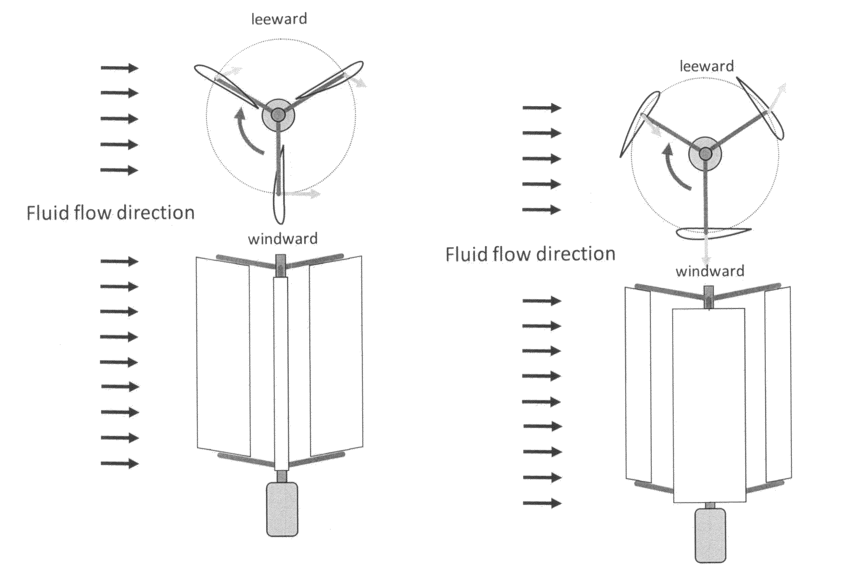
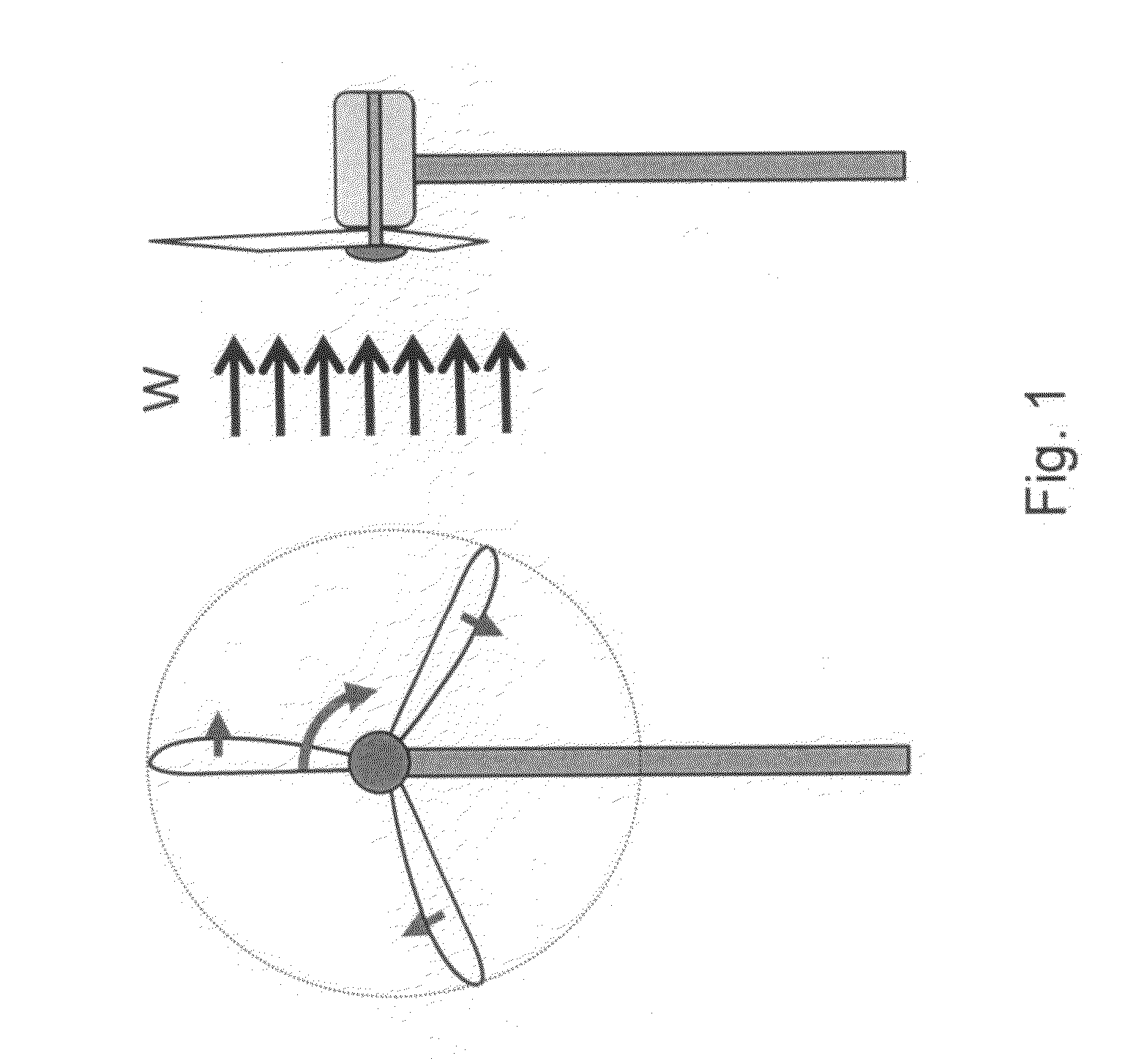
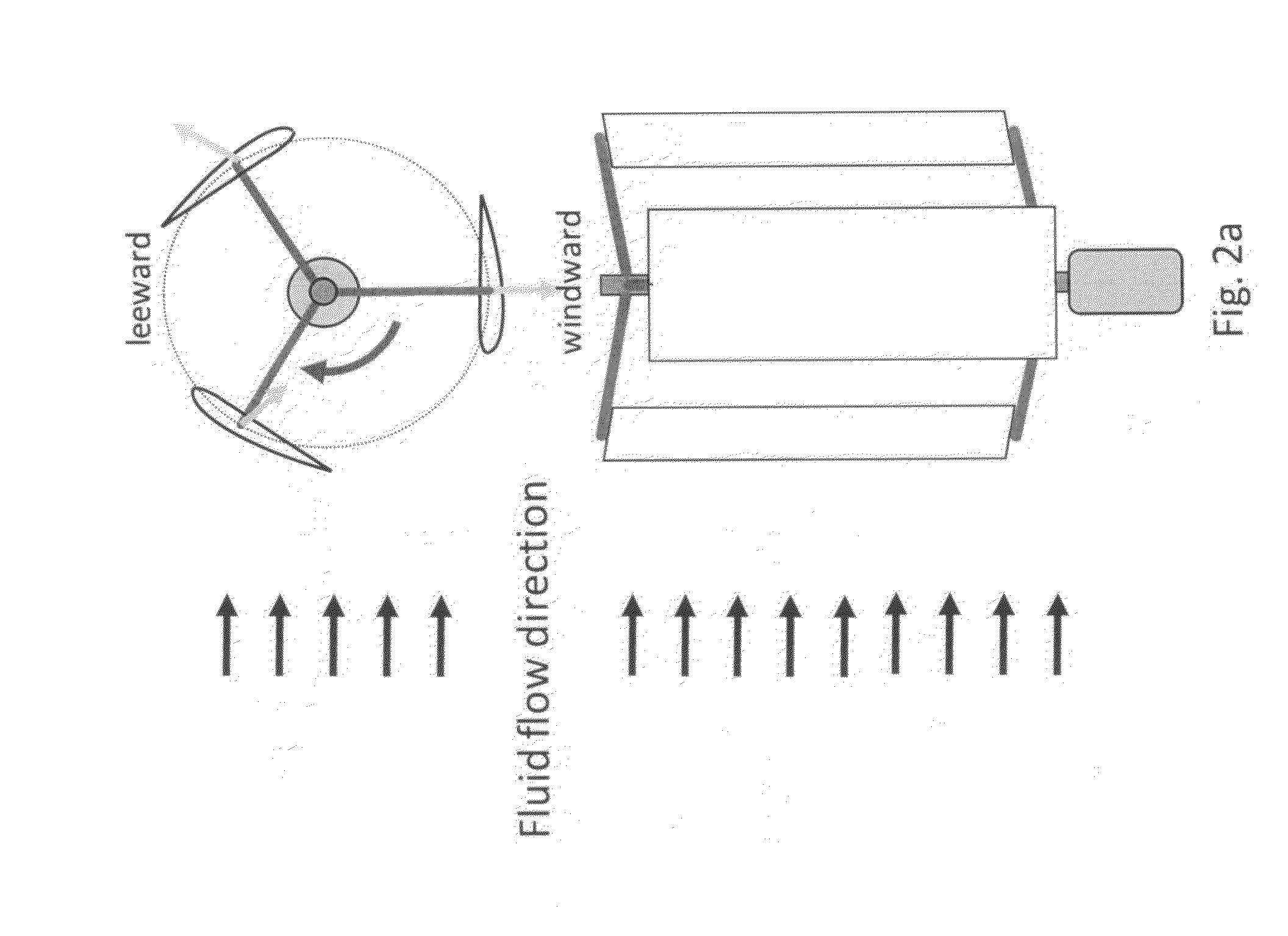
[0082]An ideal turbine has airfoil blades that interact with 100% of the fluid flow entering the turbine's swept area and operates at maximum efficiency at both low and high fluid flow speeds. This proposed design align each airfoil airfoil blade so that it rotates at a constant speed of half of the turbine itself, feathers the fluid flow (with an attack angle of 180°) at windward position, turns quickly by 180° (with an attack angle of 0°) right around the windward position, and maximizes the drag force at leeward position (with an attack angle of 90°). FIGS. 3a, 3b, and 3c show the top views of an airfoil blade at different rotational positions A, B, C, D, E, F, G, and H of an ideal cross-flow turbine at different turbine speeds.

[0083]When the turbine starts to turn from standstill, the relative velocity of the fluid flow with respect to the airfoil blade 12 is the same as the fluid flow velocity 11, as shown in FIG. 3a, since the airfoil blade's velocity 14 is zero. The aerodyna...


PUM


Abstract

This invention proposes a cross-flow turbine design with airfoil blades and self-alignment mechanisms. The airfoil blade self-alignment mechanisms rotate the airfoil blades at half of the turbine main shaft's speed and dynamically flip the blades after reaching the windward position to realign the airfoil blades or reset the attack angle of each airfoil blade so that the airfoil blade feathers the fluid flow at the windward position, generates maximum drag force at or near the leeward position, and produces both maximum lift and drag forces in between.

Description

FIELD OF THE INVENTION[0001]A turbine is a rotary mechanical device that extracts energy from a fluid flow, such as fluid flow, water, gas, or steam, and converts it into mechanical energy. The mechanical energy may drive machinery directly, such as a water pump or grinder, and is then called a wind or water mill. The mechanical energy may also be used to drive an electric generator to produce electricity, and is then called an electric power generator.[0002]Turbines can be categorized into two types based on the relative orientation between the main rotating shaft and the fluid flow. A turbine with its main rotating shaft parallel to the fluid flow direction is called an axial-flow turbine. A turbine with the main rotating shaft perpendicular to the fluid flow direction is called a cross-flow turbine. This invention applies to a cross-flow turbine for improvement of fluid-to-mechanical energy conversion efficiency.BACKGROUND—DESCRIPTION OF PRIOR ART[0003]A typical axial-flow turbin...

Claims


Application Information

Patent Timeline
Patent Type & Authority Applications(United States)
IPC IPC(8): F03D7/04
CPCF03D7/04F03D3/068Y02E10/74
Inventor LEE, CALVIN CHUNLIANG
Owner LEE CALVIN CHUNLIANG
Learn More