
Sychronous control integrated system for bridge lifting

a technology of integrated system and bridge, which is applied in the direction of bridges, bridge types, instruments, etc., can solve the problems of increased strain on the bridge body, variance in the structural force state of the bridge body, and even violation of the bridge structure, so as to improve accuracy and safety, accurate adjustment and monitoring

Inactive Publication Date: 2014-10-16
CHINA ENG CONSULTANTS +1
View PDF2 Cites 8 Cited by
  • Summary
  • Abstract
  • Description
  • Claims
  • Application Information

AI Technical Summary

Benefits of technology

The present invention provides a synchronous control integrated system for bridge lifting that uses sensors and monitors to accurately control the movement of the bridge. This system ensures that the oil pressure control and the jacks are adjusted and monitored, resulting in improved accuracy and safety during the lifting process.

Problems solved by technology

However, since the construction equipment or lifting speed in the bridge lifting course has its difference, the girders of the bridge may have variant position shift, resulting in an additional strain in the bridge body.
Further, the structural force state associated with the bridge body might have a variance due to the weight shift of the upper structure distributed on the jacks under the bridge body in the course of bridge lifting, where each of the jacks may have a weight load from tens of tons to hundreds of tons, and the aging problem and the environment associated with the bridge body.
Furthermore, the structure of the bridge structure may have an impair, a breakage and even a violation.
At this time, the variant position shift may accumulate errors owing to the increased altitude of the raised bridge, and thus increase the inclination of the bridge body.
This may not only lead to an impair to the bridge body structure, but the construction safety may be adversely affected at its worst case.
With the consideration of the repair cost, the required time, and the caused inconvenience of traffic, the total damage may be inestimable.

Method used


Image

  • Sychronous control integrated system for bridge lifting
  • Sychronous control integrated system for bridge lifting
  • Sychronous control integrated system for bridge lifting

Examples


Embodiment Construction

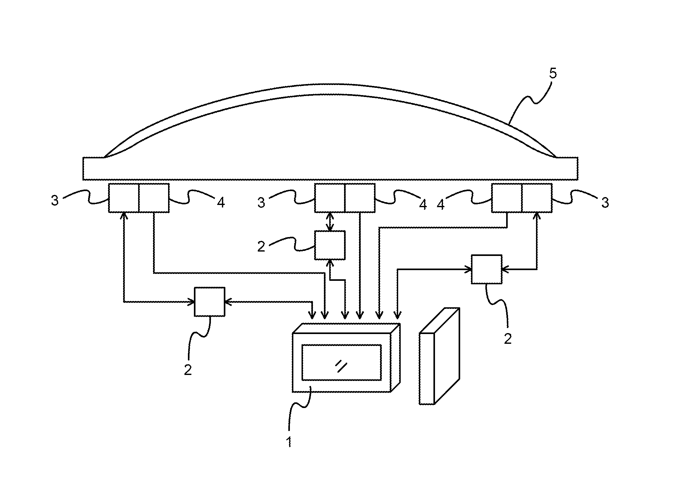
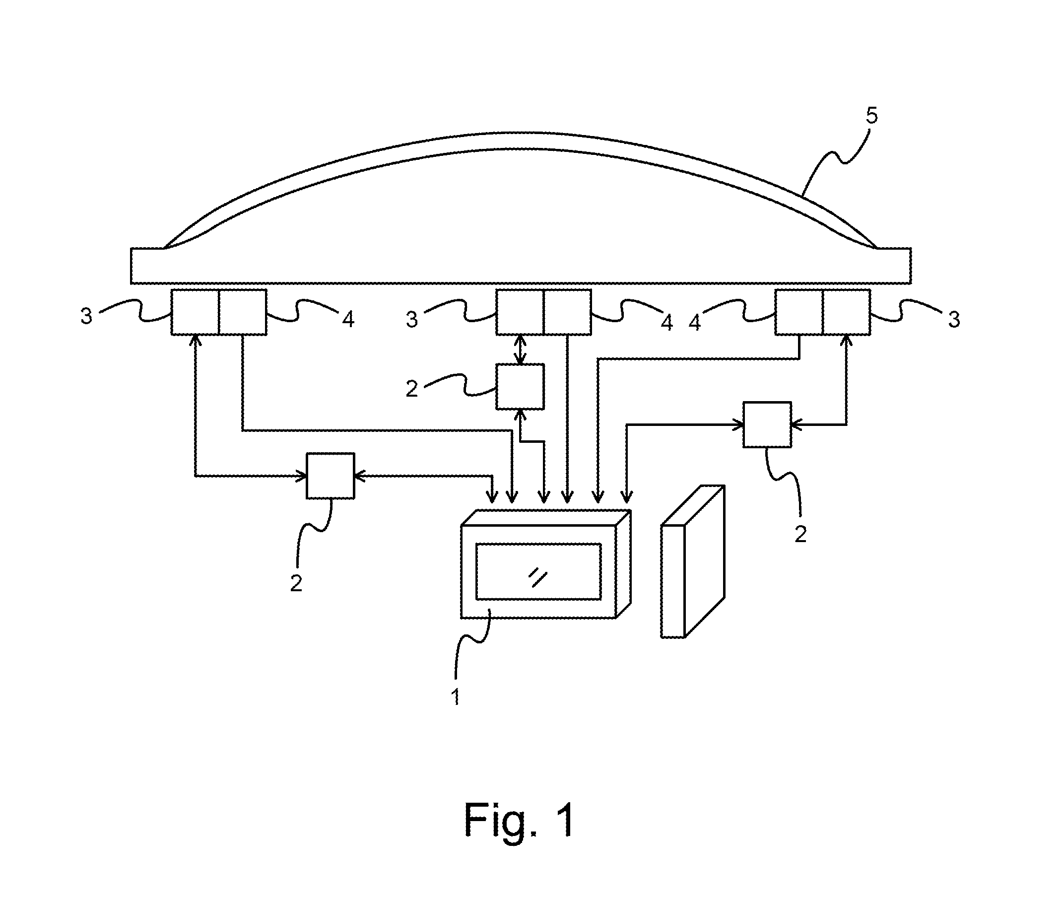
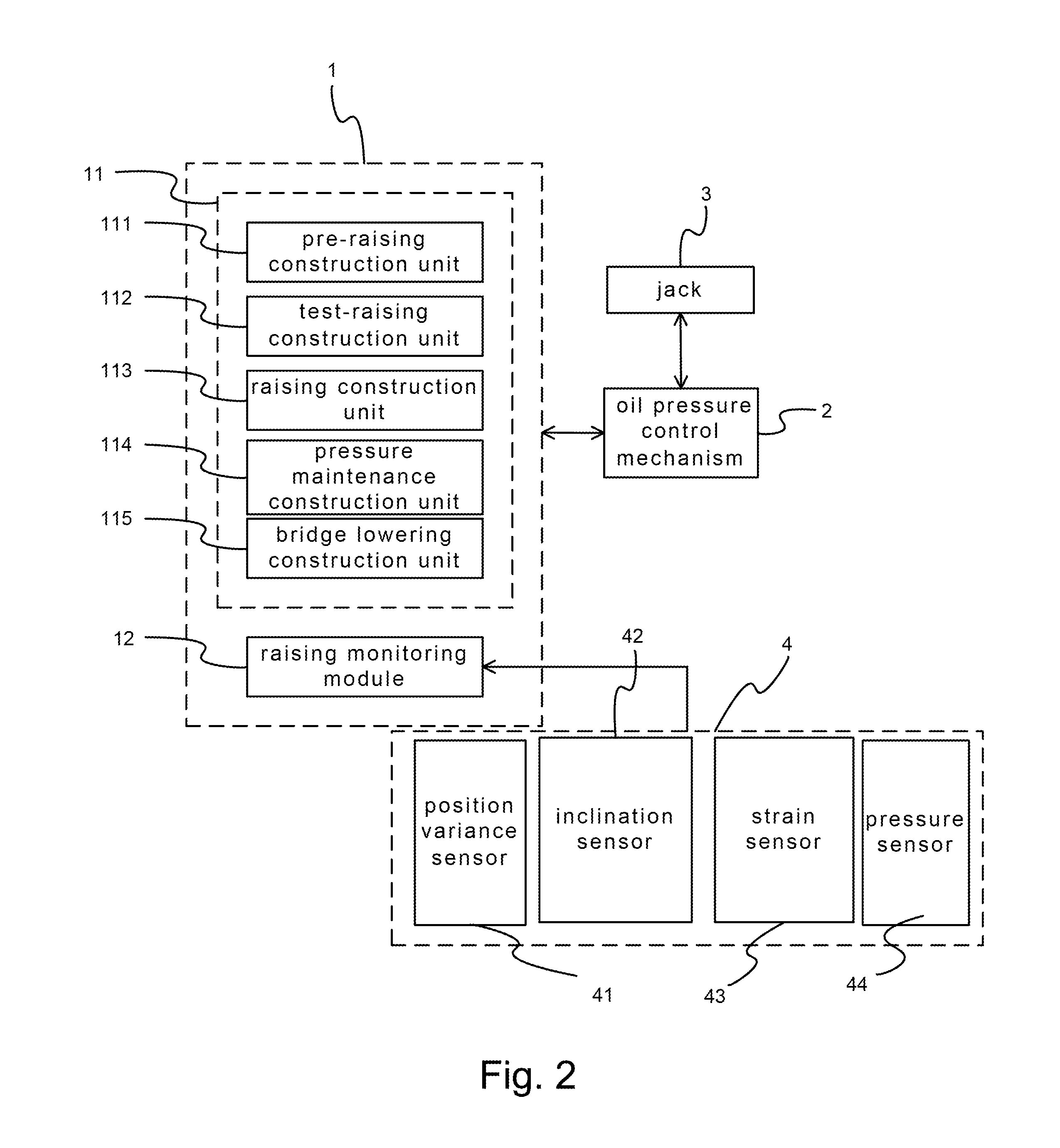
[0014]Referring to FIG. 1 and FIG. 2, a schematic diagram of a basic architecture according to the present invention; and a schematic block diagram according to the present invention are shown, respectively. As shown, a synchronous control integrated system for lifting a bridge comprises a monitor mechanism 1, an oil pressure control mechanism 2, a plurality of jacks 3, and a sensor mechanism 4.

[0015]The oil pressure control mechanism 2 is connected to the monitor mechanism 1. The plurality of jacks 3 are each connected to the oil pressure mechanism, respectively. The sensor mechanism 4 is connected to the monitor mechanism 1.

[0016]In the above, the monitor mechanism 1 comprises a lifting policy module 11 and a lifting monitor module 12. The lifting policy module 11 comprises a pre-lifting construction unit 111, a test-lifting construction unit 112, a lifting construction unit 113, a pressure maintenance construction unit 114, and a bridge lowering construction unit 115.

[0017]The se...


PUM


Abstract

A synchronous control integrated system for bridge lifting, comprising a monitor mechanism; an oil pressure control mechanism, connected to the monitor mechanism; a plurality of jacks, each connected to the oil pressure mechanism, respectively; and a sensor mechanism, connected to the monitor mechanism. As such, a shift variance generated by girders of a bridge may form a signal by using a sensor mechanism and jacks together transmitted on line to a monitor mechanism as a control parameter, so that the monitor mechanism may have an accurate adjustment and monitoring on an oil pressure control mechanism and the jacks, whereby completing the synchronous control operation for the bridge lifting course. Furthermore, the bridge lifting construction may have its improved accuracy and safety.

Description

FIELD OF THE INVENTION[0001]The present invention relates to a synchronous control integrated system for bridge lifting, and particularly to a synchronous control integrated system for bridge lifting where a shift variance generated by girders of a bridge may form a signal by using a sensor mechanism and jacks together transmitted on line to a monitor mechanism as a control parameter, so that the monitor mechanism may have an accurate adjustment and monitoring on an oil pressure control mechanism and the jacks, whereby completing the synchronous control operation for the bridge lifting course. Furthermore, the bridge lifting construction may have its improved accuracy and safety.DESCRIPTION OF THE RELATED ART[0002]At present, the bridge lifting construction method is generally implemented by screwing a supporting bracket at an outer side of an abutment or pier cap concrete structure body, whereby an operational platform for setting up a jack. Furthermore, girders of the bridge are e...

Claims


Application Information

Patent Timeline
Patent Type & Authority Applications(United States)
IPC IPC(8): E01D22/00
CPCE01D22/00E01D15/00E01D15/02G05B11/60
Inventor LIAO, CHING-LUNGCHAO, MINWANG, CHUNG-YUEMA, JIN-CHUNG
Owner CHINA ENG CONSULTANTS
Learn More