Linear drive for furniture

Inactive Publication Date: 2014-10-23
DEWERTOKIN GMBH
View PDF6 Cites 12 Cited by
  • Summary
  • Abstract
  • Description
  • Claims
  • Application Information

AI Technical Summary

Benefits of technology

[0006]Therefore the object of the invention is to provide a linear drive which is of a simple structure,

Problems solved by technology

That known construction is comparable to a certain extent with the very robust and loadable structure of the construc

Method used


Image

  • Linear drive for furniture
  • Linear drive for furniture
  • Linear drive for furniture

Examples


Embodiment Construction

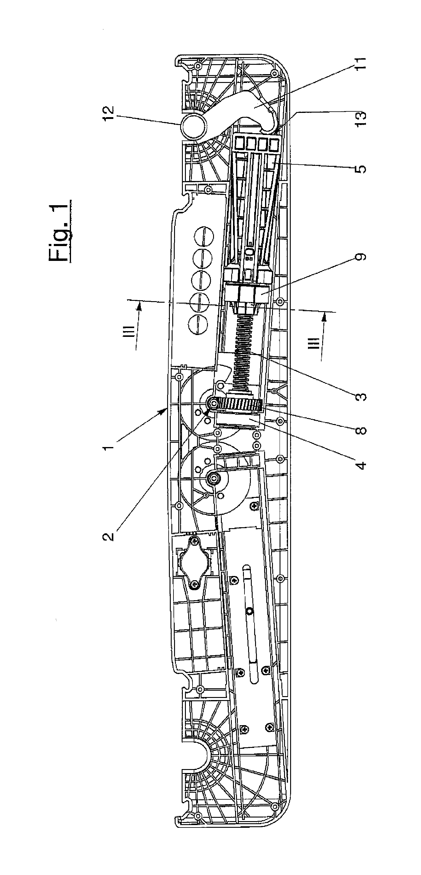
[0036]In the section shown in FIG. 1 through a linear dual drive, the two regions shown at right and left are identical. Therefore, only the structural elements arranged in the right-hand part of the gear housing 1 are described.

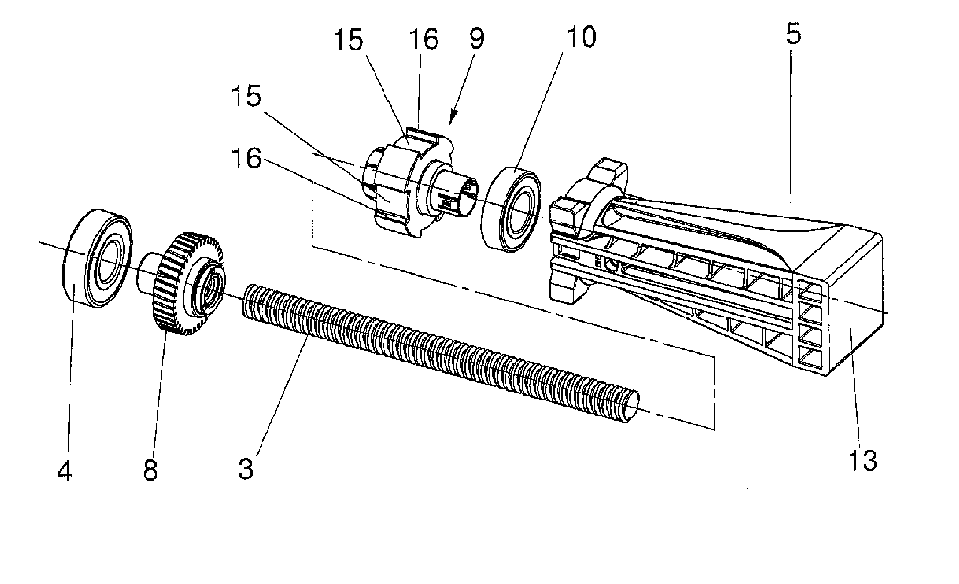
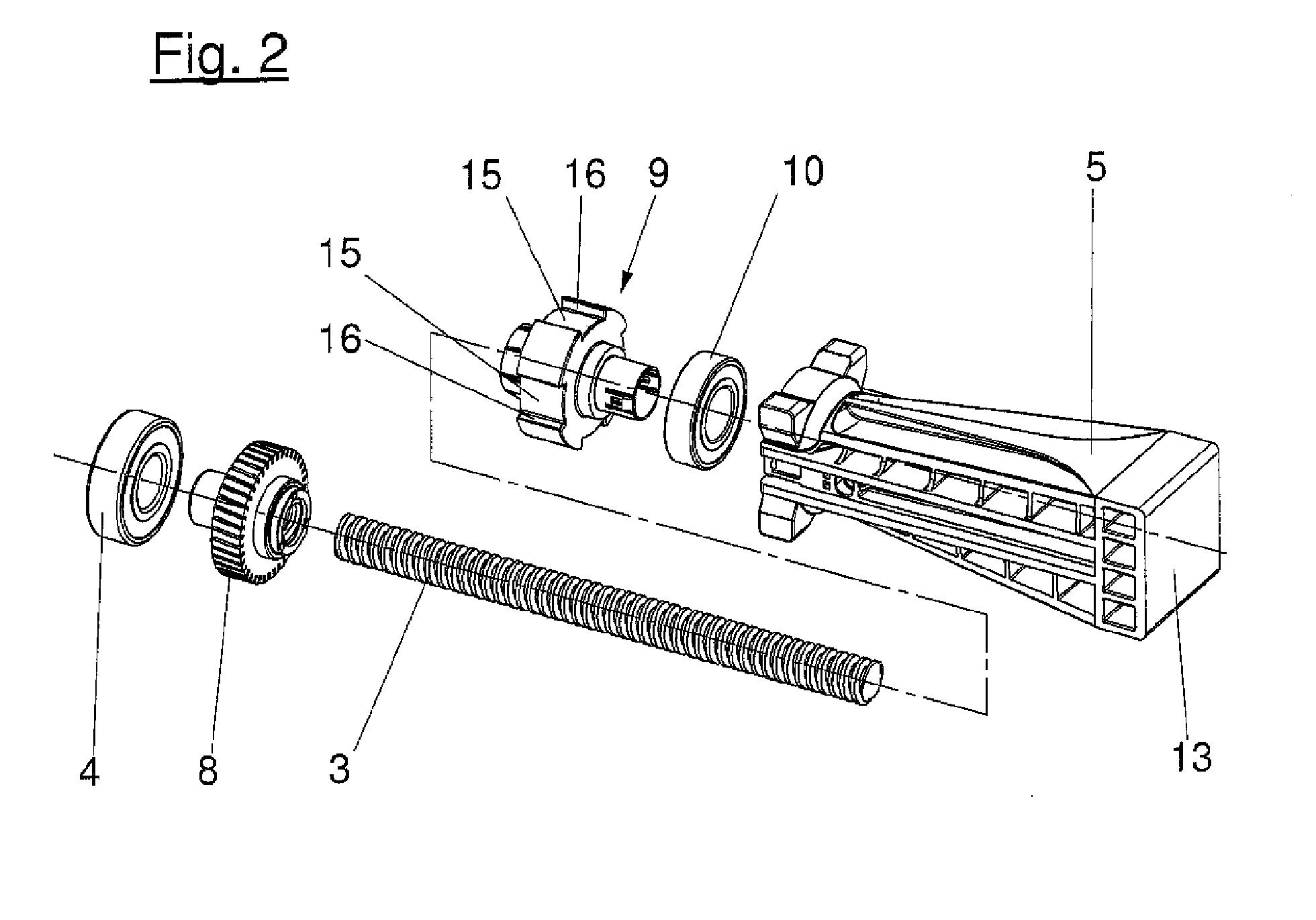
[0037]A motor (not shown) drives a threaded spindle 3 by a speed reduction gear 2. At its left-hand end the threaded spindle 3 is mounted in a bearing 4, preferably a ball bearing, in the gear housing 1. The opposite end of the threaded spindle 3 is supported by a stroke element 5, which is of a substantially square cross-section and is guided axially slidably in the gear housing 1.

[0038]Of the motor (not shown) the drawing shows only the output shaft 6 on which a worm 7 is non-rotatably arranged. The worm is in engagement with a worm gear 8, which is fixed non-rotatably and also axially immoveably on the threaded spindle 3.

[0039]In addition, carried on the threaded spindle 3 is a spindle nut 9 which, as can be seen from FIG. 2, is rotatably connected to the...


PUM


Abstract

An electromotive linear drive, in particular for adjusting movably mounted parts of lounging and seating furniture, has a drive motor, a threaded spindle, a speed-reducing gear unit arranged between the drive motor and the threaded spindle, and a spindle nut (9) located on the threaded spindle. The spindle nut is optionally lockable in the direction of rotation and movable in the axial direction of the threaded spindle, depending on the direction of rotation of the threaded spindle. A lifting element can be driven by the axial movement of the spindle nut to adjust the movable furniture parts. Such a linear drive has a simple design, is easy to assemble and operate, and guarantee a robust mounting arrangement for the drive parts.

Description

CROSS-REFERENCE TO RELATED APPLICATIONS[0001]This application is a Section 371 of International Application No. PCT / EP2012 / 069758, filed Oct. 5, 2012, which was published in the German language on May 16, 2013, under International Publication No. WO 2013 / 068184 A1 and the disclosure of which is incorporated herein by reference.BACKGROUND OF THE INVENTION[0002]The invention concerns an electric motor-actuated linear drive, in particular for adjusting moveably mounted parts of lying and seating furniture, including for the medical sector like rehabilitation organizations, care beds, etc. The drive comprises a drive motor, a threaded spindle, a speed reduction gear arranged between the drive motor and the threaded spindle, a spindle nut which is carried on the threaded spindle and which can be selectively arrested in the direction of rotation and which is displaceable in the axial direction of the threaded spindle in dependence on the direction of rotation of the threaded spindle, and ...

Claims


Application Information

Patent Timeline
IPC IPC(8): F16H25/12
CPCF16H25/12A47C20/041A61G7/018F16H25/20F16H25/2025F16H2025/2065F16H2025/2084F16H2025/209H01R4/62H01R13/447H01R31/02Y10T74/18576
Inventor DUCK, HEINRICHMARTIN, JURGEN
Owner DEWERTOKIN GMBH
Why Eureka
Try Eureka