Yaw drive for a yawing system for a wind turbine
Active Publication Date: 2014-10-23
VESTAS WIND SYST AS
View PDF10 Cites 5 Cited by
- Summary
- Abstract
- Description
- Claims
- Application Information
AI Technical Summary
Benefits of technology
This patent describes a yaw drive for a wind turbine that uses a torque limiter to control the movement of the yaw. The torque limiter is located between the motor and gear assembly, which helps minimize the amount of torque required and reduces the size of the limiter. By controlling a hydraulic preload system, a reliable and known preload force can be maintained during the lifetime of the torque limiter. Additionally, the adjusting mechanism can be performed easily and quickly, reducing downtime for the wind turbine.
Problems solved by technology
However, such brakes tend to be inaccurate, thereby providing a too high braking force and introducing loads in the yaw drive, and possibly in the entire yawing system, and even in the entire wind turbine.
One disadvantage of this is that it is necessary to disassemble the gear system in order to provide service or adjustment to the torque limiter.
Method used
View moreImage
Smart ImageViewing Examples

Examples
first embodiment
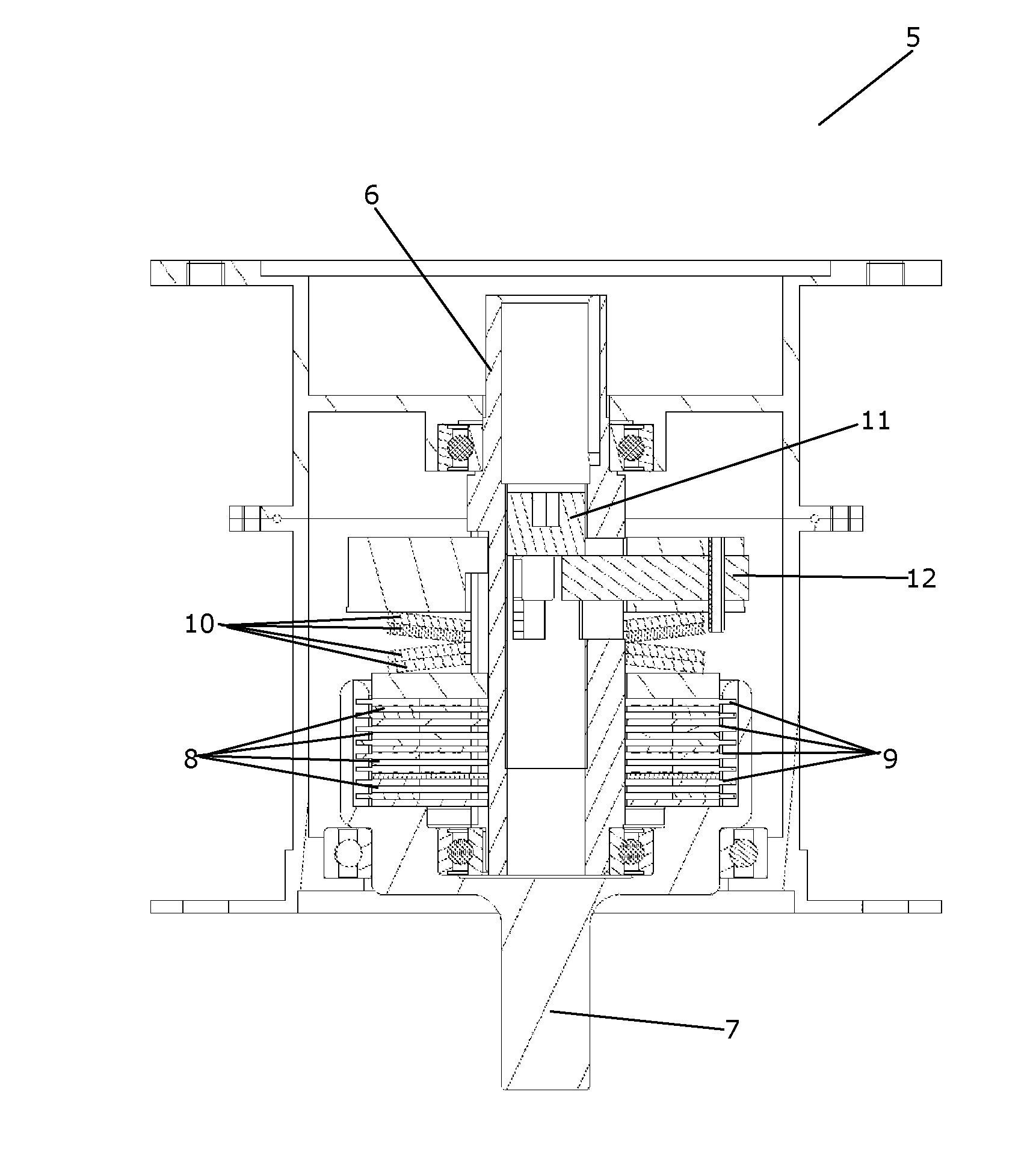
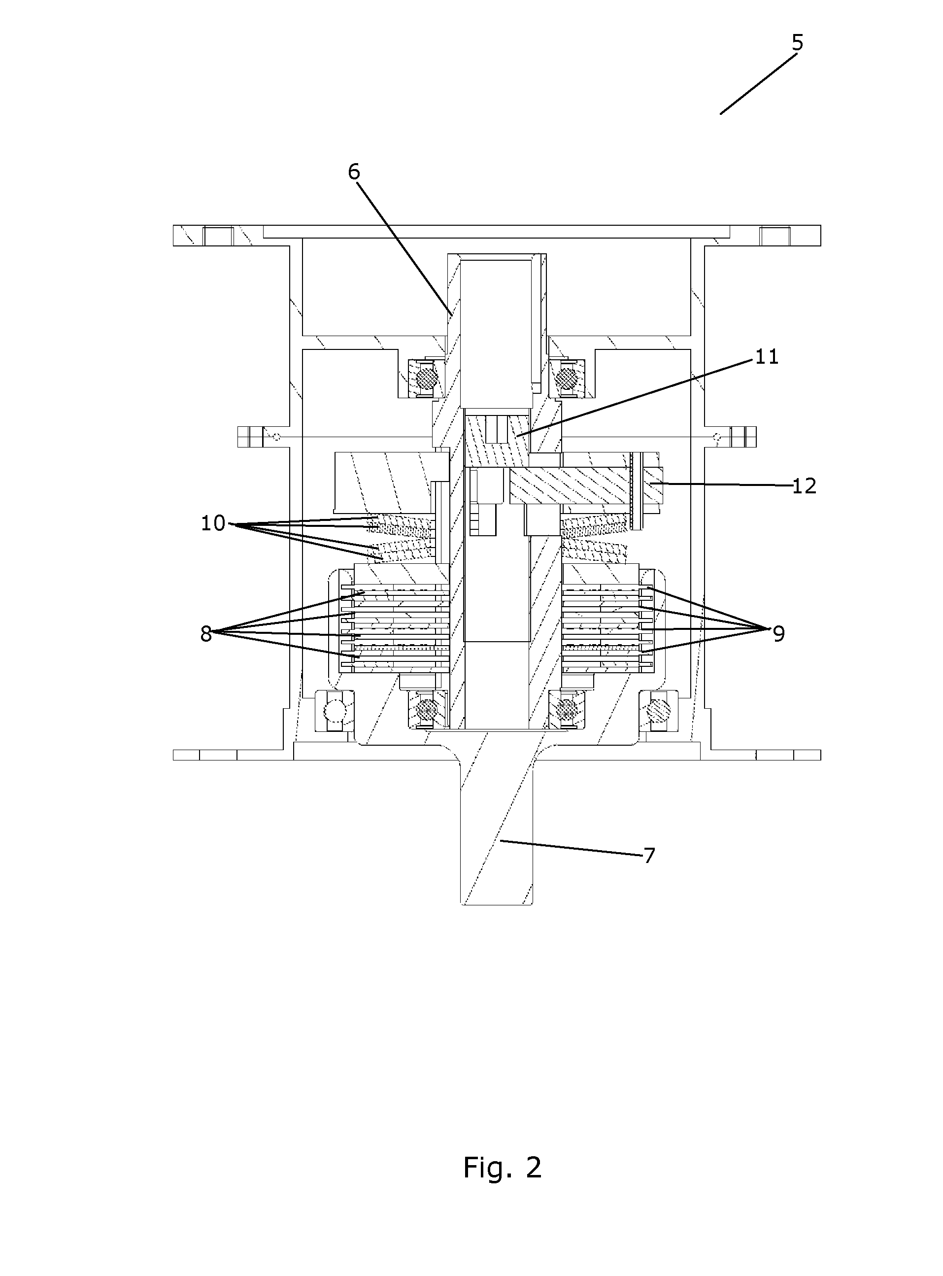
[0033]FIG. 2 is a cross sectional view of a torque limiter for a yaw drive according to the invention,
second embodiment
[0034]FIG. 3 is a cross sectional view of a torque limiter for a yaw drive according to the invention,
[0035]FIGS. 4 and 5 illustrate a slotted disc spring for use in a torque limiter for a yaw drive according to an embodiment of the invention, and
[0036]FIG. 6 is a graph illustrating the spring characteristic for the slotted disc spring of FIGS. 4 and 5.
Login to View More PUM
 Abstract
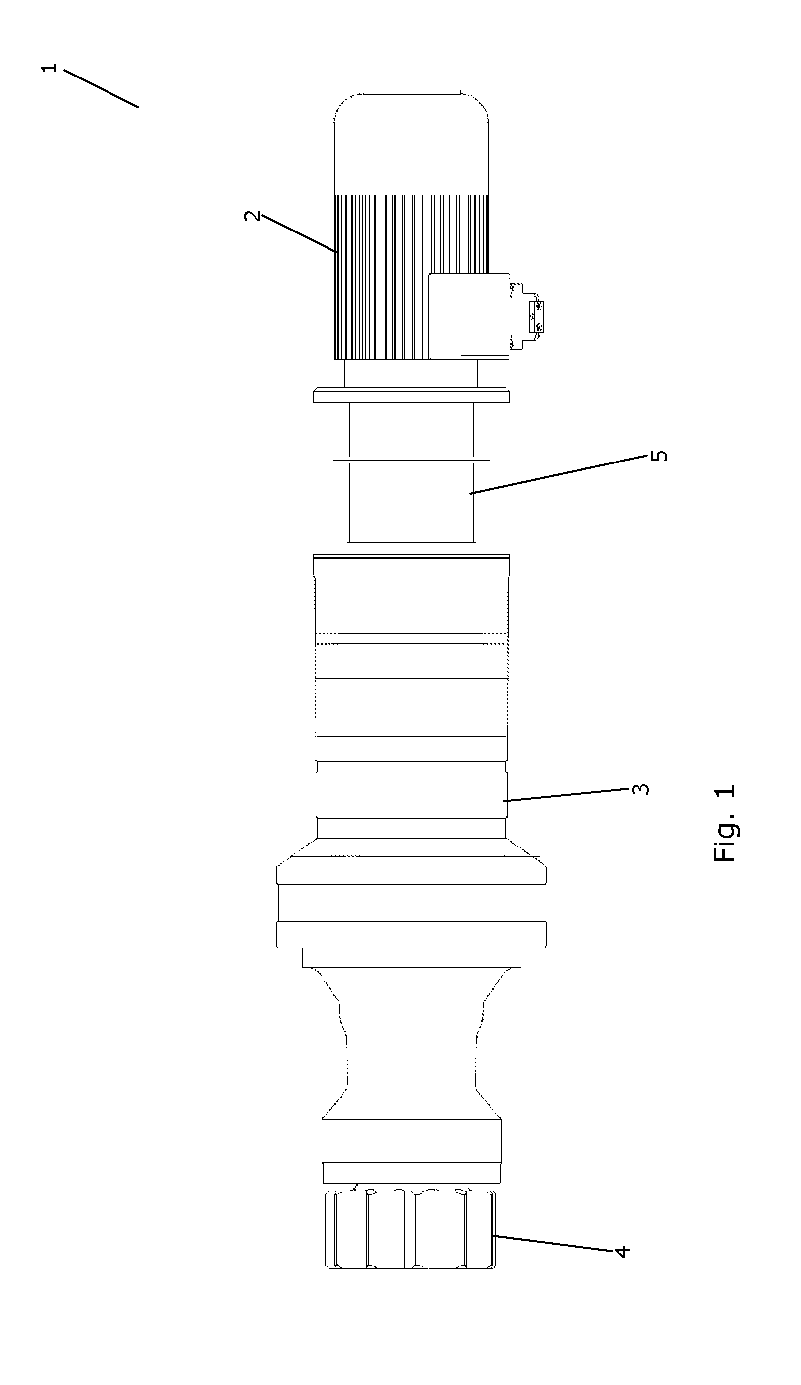
A yaw drive (1) for a yawing system for a wind turbine, the yaw drive (1) comprising a motor (2), a gear assembly (3) operationally connected to the motor (2), and a torque limiter (5). The torque limiter (5) is arranged detachably between the motor (2) and the gear assembly (3), in such a manner that the torque limiter (5) is capable of transferring torque between the motor (2) and the gear assembly (3), and the torque limiter (5) being capable of limiting torque transfer between the motor (2) and the gear assembly (3) when the torque applied to the torque limiter (5) exceeds a threshold value. A torque transferring part of the torque limiter (5) comprises a first set of discs connected to a rotating output shaft of the motor (2) and a second set of discs connected to a rotating input shaft of the gear assembly (3), the discs (8) of the first set of discs being arranged interleaved with the discs (9) of the second set of discs, thereby forming a stack of discs. A friction between the discs (8) of the first set of discs and the discs (9) of the second set of discs provides torque transfer between the discs (8, 9). The discs (8, 9) are allowed to rotate relative to each other when an applied torque overcomes the friction between the discs (8, 9). The torque limiter (5) is provided with a preload mechanism, e.g. in the form of slotted disc springs (10), arranged to apply a preload force to the stack of discs in such a manner that the preload force defines the friction between the discs (8, 9).
Description
FIELD OF THE INVENTION[0001]The present invention relates to a yaw drive for a yawing system for a wind turbine. The yaw drive of the invention comprises a torque limiter for limiting torque loads in the yaw drive, thereby reducing wear on the yaw drive.BACKGROUND OF THE INVENTION[0002]When a yaw drive is operated, a motor provides high speed rotation for an output shaft. The output shaft is connected to an input shaft of a gear assembly. In the gear assembly the rotational speed is reduced, and an output gear wheel of the gear assembly is arranged in engagement with a large gear ring, thereby causing a nacelle of a wind turbine to rotate about a substantially vertical axis.[0003]The motor of the yaw drive is often provided with a brake, such as an electro-magnetic brake, which is used when a yawing movement is to be stopped, and when a yawing position is to be maintained. However, such brakes tend to be inaccurate, thereby providing a too high braking force and introducing loads in...
Claims
Login to View More Application Information
Patent Timeline
 IPC IPC(8): F16D7/02
CPCF16D7/027F03D7/0204F16D43/216F05B2260/4023F05B2270/335Y02E10/72
Inventor RASMUSSEN, LARS VERMUND
Owner VESTAS WIND SYST AS