Coalescing filter element and filter assembly therefore

a filter element and filter assembly technology, applied in the direction of filtration separation, machine/engine, separation process, etc., can solve the problems of increasing wear, promoting microbial growth, seizure of close tolerance parts, etc., and achieve the effect of cost-effectiveness

Active Publication Date: 2014-10-23
SCHROEDER INDS L L C
View PDF5 Cites 29 Cited by
  • Summary
  • Abstract
  • Description
  • Claims
  • Application Information

AI Technical Summary

Benefits of technology

[0011]This invention is directed to a cost effective, efficient, coalescing filter element and coalescing filter assembly. ...

Problems solved by technology

Water in a vehicle fuel system can reduce lubricity causing seizure of close tolerance parts and increased wear.
Water in fuel storage tanks may cause rust and can promote microbial growth.
In warm weather, microbial ...

Method used


Image

  • Coalescing filter element and filter assembly therefore
  • Coalescing filter element and filter assembly therefore
  • Coalescing filter element and filter assembly therefore

Examples


Embodiment Construction

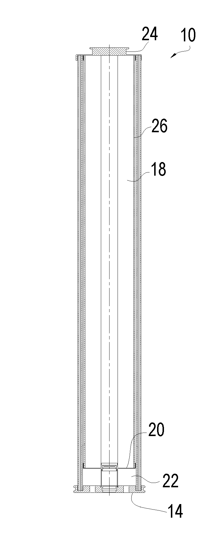
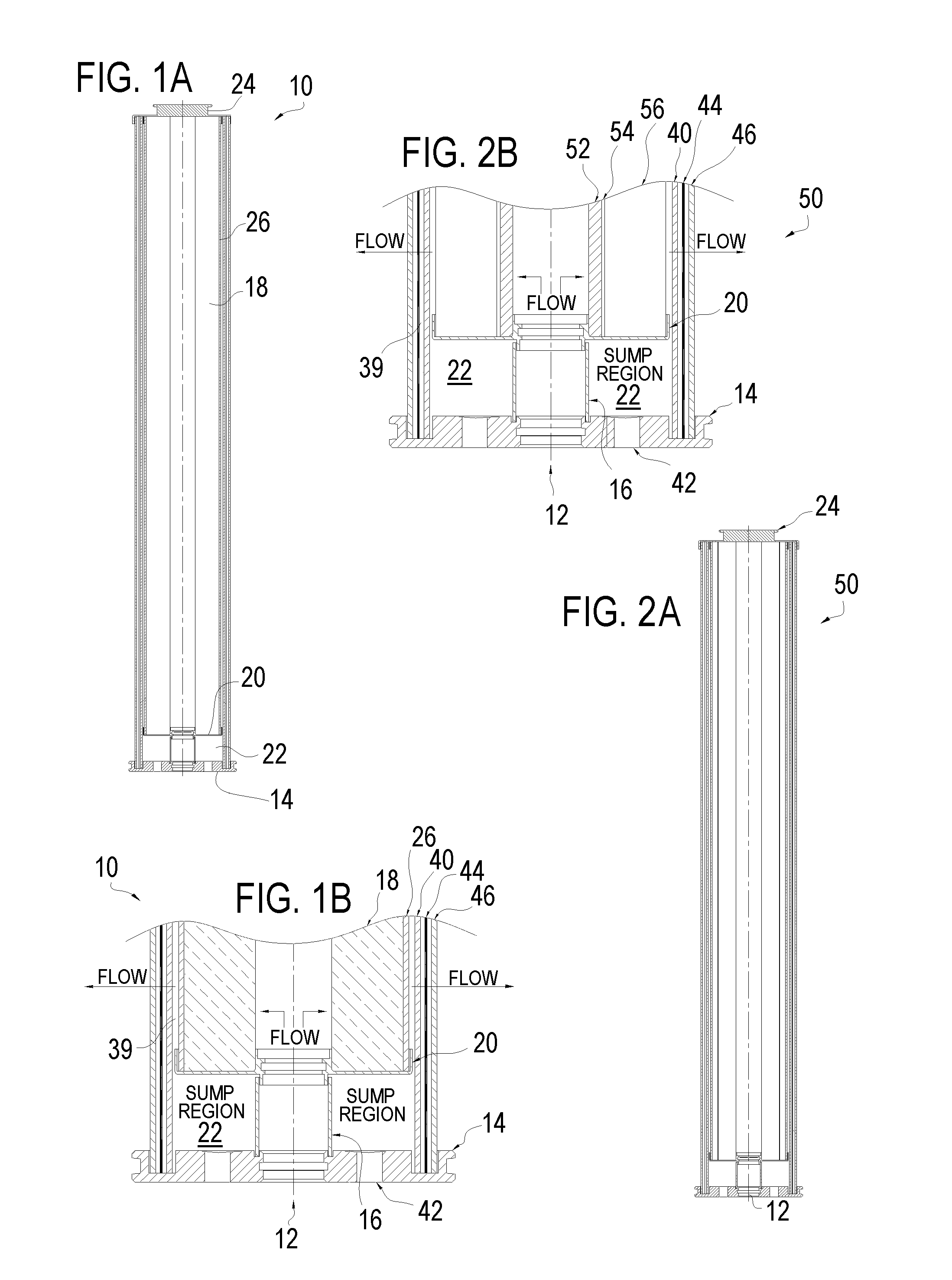
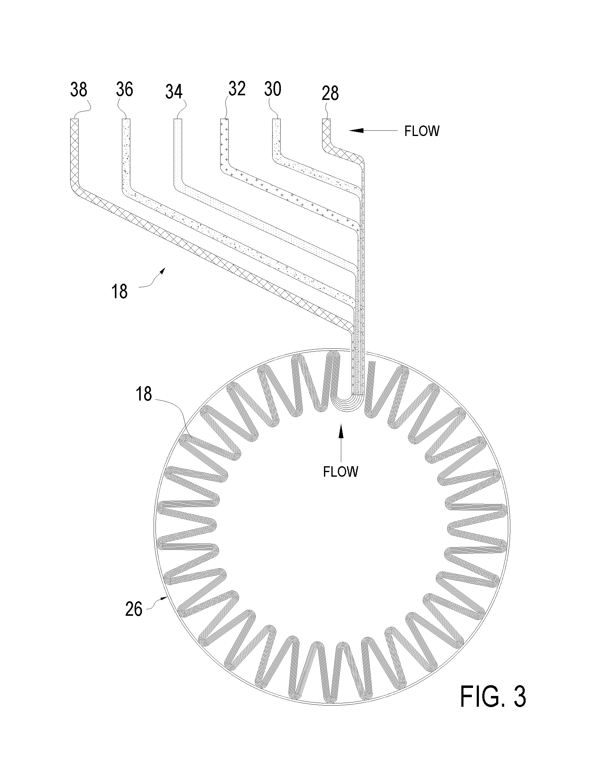
[0023]This invention is directed to a cost effective, efficient, coalescing filter element and coalescing filter assembly. The invention provides an integrated filter element with a three stage design with a hydrophobic or hydrophilic coalescing layer.

[0024]It is noted that, as used in this specification and the appended claims, the singular forms “a,”“an,” and “the” include plural referents unless expressly and unequivocally limited to one referent.

[0025]For the purposes of this specification, unless otherwise indicated, all numbers expressing quantities of ingredients, reaction conditions, and so forth used in the specification and claims are to be understood as being modified in all instances by the term “about.” Accordingly, unless indicated to the contrary, the numerical parameters set forth in the following specification and attached claims are approximations that may vary depending upon the desired properties sought to be obtained by the present invention. At the very least, ...


PUM

PropertyMeasurementUnit
Hydrophilicityaaaaaaaaaa
Hydrophobicityaaaaaaaaaa

Abstract

A coalescing filter element provides an integrated filter element with a three stage design with a hydrophobic or hydrophilic coalescing layer. A coalescing filter element comprises: a) At least one particulate filtration layer; b) A coalescing layer promoting coalescing of water particles, wherein the coalescing layer is downstream of the at least one particulate filtration layer relative to the flow of fluid through the element; c) An annular coalescing space downstream of the coalescing layer; d) A sump in a lower portion of the filter element in fluid communication with the annular coalescing space; and e) A hydrophobic layer downstream of the annular coalescing space, wherein fluid being cleaned by the element flows through the hydrophobic layer. The coalescing layer may be a hydrophobic or a hydrophilic coalescing layer. A filter assembly will include the coalescing filter element of the present invention.

Description

RELATED APPLICATIONS[0001]This application claims priority to U.S. patent application Ser. No. 61 / 778,340 filed Mar. 12, 2013, entitled “Coalescing Filter Element and Filter Assembly Therefore” which application is incorporated herein by reference in its entirety.BACKGROUND INFORMATION[0002]1. Field of the Invention[0003]The present invention relates to filter elements and filter assemblies, and more particular to coalescing filter element and coalescing filter assembly.[0004]2. Background Information[0005]Advances in diesel engine fuel injection systems have been instrumental in complying with current and future emission standards. Higher pressure fuel produces a finer mist of fuel, which burns cleaner. Common rail injection systems run at higher pressures and allow more injections per combustion cycle improving fuel economy, better engine performance and lower noise. Higher pressure fuel injector systems (e.g., 20,000+ psi) have tighter tolerances and require substantially free wa...

Claims


Application Information

Patent Timeline
IPC IPC(8): B01D29/00B01D29/56
CPCB01D29/56B01D29/00B01D29/232B01D36/003B01D2201/188C10G33/06Y10S210/05B01D17/0208B01D17/0214B01D17/04B01D17/045B01D27/06B01D29/21F02M37/24
Inventor BORTNIK, CHRISSURDICK, SCOTTSCHMITT, MICHAEL JEVANOVICH, STEVEN RSCHUNK, ANDREAS
Owner SCHROEDER INDS L L C
Why Eureka
Try Eureka