Coaxial rotor/wing aircraft

Inactive Publication Date: 2014-10-23
GAONJUR RAJESH
View PDF0 Cites 44 Cited by
  • Summary
  • Abstract
  • Description
  • Claims
  • Application Information

AI Technical Summary

Benefits of technology

[0009]It is the main object of this invention to provide a method and system to enable efficient and safe transition between

Problems solved by technology

So far, no practical and reliable rotor/wings aircraft is known to exist till date.
The main problem in implementing the rotor/wing concept lies in the difficulty to achieve transition between the rotary-wing and the fixed-wing mode.
As the rotor/wing is slowed down to a stop, it becomes seriously affected by the dissymmetry of lift caused by the advancing portion and retreating portion of the rotor/Wing.
The aircraft is subjected to dangerous pitching, rolling movements and loss of altitude, with serious consequences.
However, it is physically not possible to reduce the transition time beyond certain point.
The vertical stabiliser would need to be excessively out of proportion to compensate the large reaction force and is not practical due to extra weigh and drag penalty.
During the prologue transition, the aircraft is vulnerable as it continues to experience unbalance lateral lift.
The combination of these two forces makes transition between rotary-win

Method used


Image

  • Coaxial rotor/wing aircraft
  • Coaxial rotor/wing aircraft
  • Coaxial rotor/wing aircraft

Examples


embodiment 202

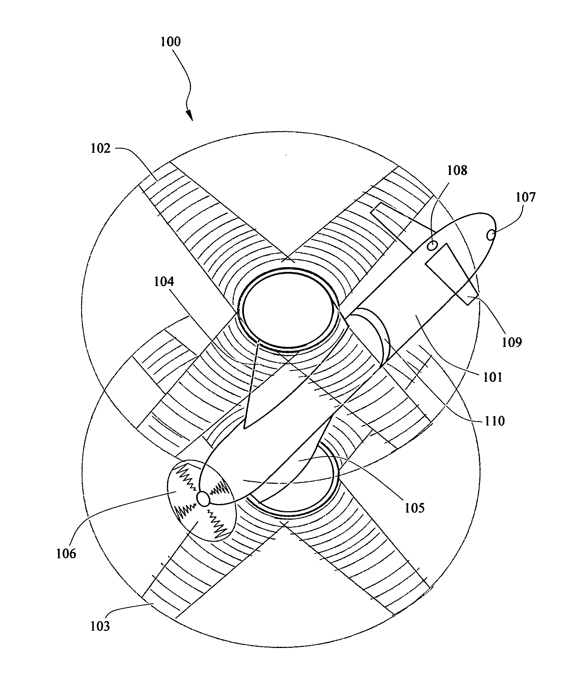
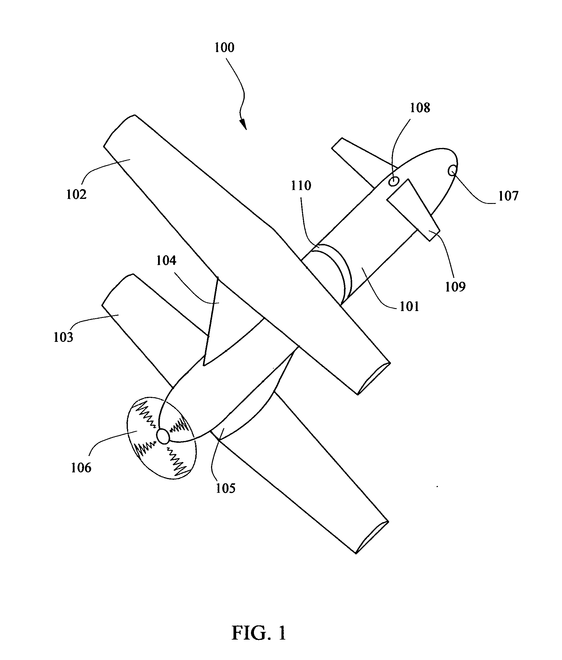
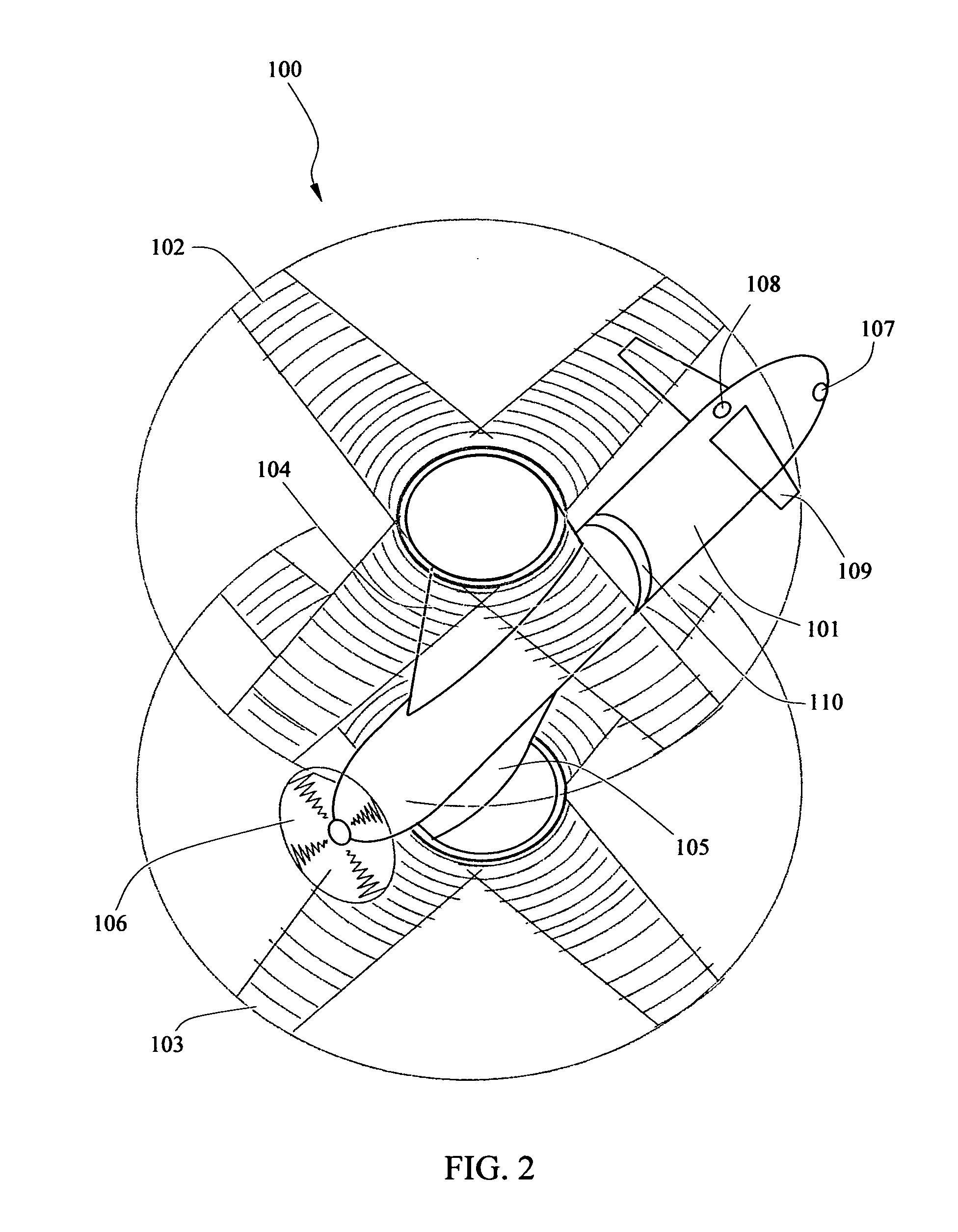
[0045]For even greater speed, the initial biplane configuration can be modified further during fixed-wing mode. As shown in FIG. 8, the rotor / wings 102 and 103 of the embodiment 202 may be pivoted about their transmission shafts, so that they form two symmetrically opposing oblique wings with a high aspect ratio. This is carried out by the positioning mechanism 20 turning the shaft 22 by a certain define amount. In other embodiments, the aircraft may include feature which independently position the rotor / wings so that one rotor / wing is aligned with the longitudinal axis of the fuselage and the other rotor / wing is maintained transverse to the longitudinal axis or in an oblique orientation to the fuselage to provide lift in a single wing configuration.

embodiment 201

[0046]In some other embodiment the lower or upper or both rotor / wings may be retracted or folded in a variety of ways so as to operate as vertical stabiliser. For example as shown in FIG. 6, sections of the lower-wing 103 are folded downward and used as twin vertical stabilisers. In other embodiments, the lower / wing 103 may be flipped in an inverted V-tail configuration. In yet other embodiment 201 as shown in FIG. 7, the rotor / wing 102 is folded upward in a dihedral configuration and the second rotor / wing 103 is folded downward in an anhedral configuration. This configuration reduces the interference between the two rotor / wings and at the same time operates as vertical stabilisers. As shown in FIG. 4-7, in the embodiments of the aircraft designed for high speed, the masts fairing 104 and 105 are built short so as to provide stronger support for the rotor / wings.

[0047]In the fixed-wing mode, the center of lift of the aircraft 100 is ahead of the axis of rotation of the rotor / wings, a...


PUM


Abstract

A system and method which enable efficient, rapid and safe transition between rotary-wing and fixed-wing flight mode in rotor/wings aircrafts is disclosed. The aircraft comprises of two rotor/wings on the same axis of rotation, one above the fuselage and the other one under the fuselage. During rotary-wing mode, the rotor/wings rotate coaxially and provide vertical lift. During transition between rotary-wing and fixed-wing modes, the synchronised operation of the two rotor/wings maintains lateral symmetry of lift on the aircraft. The reaction of the rotor/wings on the fuselage is also canceled. During fixed-wing flight mode, the two rotor/wings are stopped and locked in a biplane configuration, both providing lift as fixed wings. The rotor/wings may be further reconfigured for higher subsonic or supersonic speed. Tandem and multiple rotor/wings aircrafts with increased cargo capacity, speed and range, comprise of multiple of these coaxial rotor/wings.

Description

FIELD OF THE INVENTION[0001]The invention relates to a type of vertical take-off and landing aircraft generally referred as rotor / wing or stop-rotor aircraft.BACKGROUND[0002]One of the most promising vertical take-off and landing aircrafts (VTOL) is known in as the stop-rotor or the rotor / wing aircraft. The concept behind this type of aircraft is using a set of wings selectively in a rotary-wing mode or in a fixed-wing mode, in order to produce vertical lift. In the rotary-wing mode, the rotor / wing rotates in a horizontal plane to produce vertical lift similar to a helicopter. In the fixed-wing mode, the rotation of the rotor / wing is stopped and positioned traverse to the fuselage, in order to produce vertical lift similar to the fixed wings of an airplane.[0003]The rotor / wing aircrafts have many advantages over other concepts of VTOL aircrafts such as, compound-helicopters, tilt-rotor aircrafts, and even unpowered rotary-wings aircrafts commonly known as gyroplanes. The wingspan of...

Claims


Application Information

Patent Timeline
IPC IPC(8): B64C27/24
CPCB64C27/24B64C27/10B64C27/14B64C27/26
Inventor GAONJUR, RAJESH
Owner GAONJUR RAJESH
Why Eureka
Try Eureka