Phase-locked loop device with managed transition to random noise operation mode

a phase-locked loop and operation mode technology, applied in the direction of electrical equipment, pulse automatic control, etc., can solve the problems of wasting time, capturing noise within the loop-control frequency, and starting the lock acquisition, so as to achieve rapid reaction to lock state loss, easy to produce, and easy to produce

Active Publication Date: 2014-10-23
ASAHI KASEI ELECTRONICS CO LTD
View PDF3 Cites 13 Cited by
  • Summary
  • Abstract
  • Description
  • Claims
  • Application Information

AI Technical Summary

Benefits of technology

[0014]Hence, during the operation of the PLL device, test i allows gradual reduction of the values for the proportional and integral coefficients of the loop filter, while ensuring that the lock state is maintained. Test ii ensures that the lock state is automatically tracked again and recovered if lost at any time during the PLL operation. Progressive reduction of the proportional and integral coefficients is thus provided so that rapid lock acquisition is first performed. Then, progression until the random noise operation mode is achieved, with values for the proportional and integral coefficients appropriate for each stage of this progression. The risk for losing the lock state can thereby be reduced.
[0016]For example, the phase comparator may be adapted so that the error signal equals a first error signal value as long as the phase time-shift of the frequency-converted signal relative to the reference signal is positive, and a second error signal value which is different from the first one as long as the phase time-shift is negative. Such embodiments are simple and easy to produce, and the lock detector may be connected at an input to the comparator output.
[0017]In some embodiments, the lock detector may be adapted so that the lock condition includes a count number higher than a threshold number for successive durations which are each less than a second duration threshold, these durations existing between two successive sign reversals of the phase time-shift of the frequency-converted signal relative to the reference signal. Such embodiments of the lock detector are simple and easy to produce.
[0018]Advantageously, the loop controller may be further adapted in some embodiments so that the first duration threshold which is used in test ii is smaller when test ii is executed while current values are used respectively for the proportional and integral coefficients, when compared to test ii being executed while other values which are respectively larger than the current values are used for the proportional and integral coefficients. Rapid reaction to lock state loss can thus be achieved during the random noise operation of the PLL device.

Problems solved by technology

Otherwise, lock acquisition is started over, wasting time until the clock signal which is produced by the PLL device can be used again.
However, continuing to decrease the phase oscillation magnitude leads to capturing noise within the loop-control of the frequency of the PLL-produced clock signal.
However, such a PLL device does not detect that the lock state is actually obtained, and it cannot reach the random noise operation mode.

Method used


Image

  • Phase-locked loop device with managed transition to random noise operation mode
  • Phase-locked loop device with managed transition to random noise operation mode
  • Phase-locked loop device with managed transition to random noise operation mode

Examples


Embodiment Construction

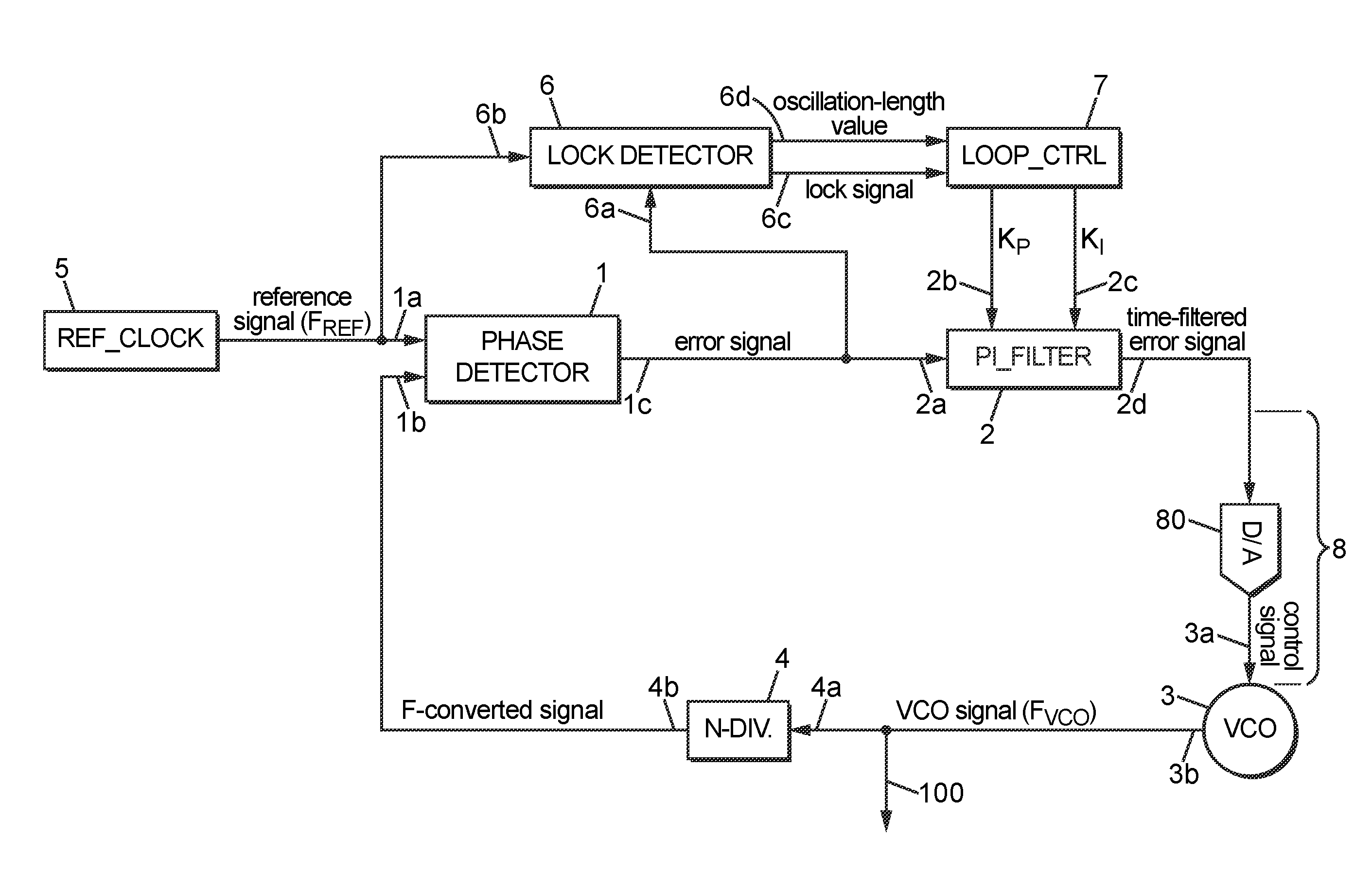
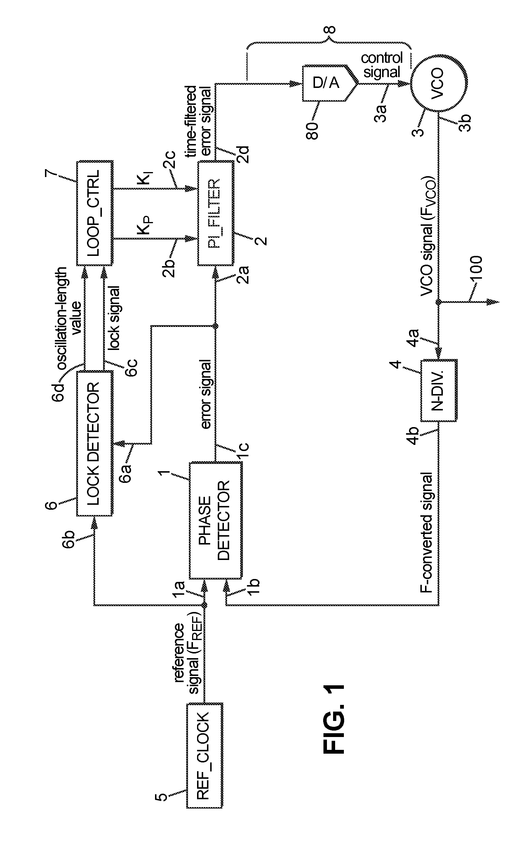
[0036]With reference to FIG. 1, which is a block diagram of a PLL device according to some embodiments, the reference numbers indicated therein have the following meanings:[0037]1 a phase comparator, denoted PHASE DETECTOR, with inputs respectively labelled 1a and 1b, and output 1c [0038]2 a loop filter, denoted PI_FILTER, with signal input 2a, configuration inputs 2b and 2c, and signal output 2d [0039]3 a voltage-controlled oscillator (VCO) module, with control input 3a dedicated for entering a control signal, and output 3b for producing a VCO signal[0040]4 a frequency converter, denoted N-DIV., with input 4a and output 4b [0041]5 a reference clock, denoted REF_CLOCK, for supplying a reference signal which has a reference frequency FREF [0042]6 a lock detector, with detector inputs respectively labelled 6a and 6b, and outputs 6c and 6d [0043]7 a loop controller, denoted LOOP_CTRL[0044]8 a control connection, extending from the filter output 2d to the control input 3a of the VCO mod...


PUM


Abstract

A phase-locked loop device is configured to manage a transition from a relaxation-oscillation mode to a random noise operation mode. It is designed for progressively reducing proportional and integral coefficients that are implemented in a loop filter of the PLL device. Recovering the last values formerly used for the proportional and integral coefficients is also provided, in case the PLL lock state is lost. Such transition management may be combined with using a voltage-controlled oscillator within the PLL device, which has several control inputs.

Description

[0001]This application claims the priority and benefit of EP patent application no. EP 13305526.9, filed on Apr. 22, 2013, to Asahi Kasei Microdevices Corporation of Japan, entitled “Phase-Locked Loop Device with Managed Transition to Random Noise Operation Mode,” which is hereby incorporated by reference in its entirety.TECHNICAL FIELD[0002]The invention relates generally to a phase-locked loop (PLL) device with a bang-bang non-linear phase detector and managed transition to random noise operation mode. It also relates generally to a process for operating a PLL device.BACKGROUND[0003]PLL devices are core elements for frequency synthesizers implemented in electronic circuits or radio-transmission units. There is a need for reducing the lock time and improving the operation stability of PLL devices.[0004]A PLL device with bang-bang non-linear phase detector can generally operate in two successive operation modes from an initial start. The first operation mode may be a relaxation-osci...

Claims


Application Information

Patent Timeline
Patent Type & Authority Applications(United States)
IPC IPC(8): H03L7/095
CPCH03L7/095H03L7/1075H03L2207/06
Inventor CANARD, DAVID
Owner ASAHI KASEI ELECTRONICS CO LTD
Why Eureka
Try Eureka