Filling liquid for distribution of ink jet head, ink jet head, and distribution method for ink jet head

a technology liquid filling, which is applied in the direction of printing, inks, domestic applications, etc., can solve the problems of degrading the discharge performance of ink jet head, increasing the above-mentioned problem, and thickening or solidifying the ink, so as to prevent the degradation of discharge performance

Active Publication Date: 2014-10-23
COPYER
View PDF6 Cites 14 Cited by
  • Summary
  • Abstract
  • Description
  • Claims
  • Application Information

AI Technical Summary

Benefits of technology

[0014]The present invention has been made so as to solve the above-mentioned problems in the related art. That is, the present invention provides: a filling liquid for distribution of an ink jet head capable of effectively preventing the degradation in discharge performance and printing quality, in particular, the occurrence of “misdirection print”, involved in, for example, the thickening and solidification of ink caused by long-term conservation, the contamination of the surface of a heater, and the liquid pool of a discharge port peripheral portion; and an ink jet head and a distribution method for an ink jet head each using the filling liquid for distribution.
[0015]The inventors of the present invention have earnestly studied the above-mentioned problems and found that the problems can be solved by accurately controlling the composition and physical properties of a filling liquid for distribution, thereby achieving the present invention. That is, according to some embodiments of the present invention, there are provided a filling liquid for distribution of an ink jet head, an ink jet head, and a distribution method for an ink jet head described below.
[0022]The filling liquid for distribution, the ink jet head, and the method of distributing the ink jet head according to the invention can effectively prevent the degradation in discharge performance and print quality, in particular, the occurrence of the “misdirection print” caused by the thickening and solidification of the ink for the long-term conservation, the contamination of the surface of the heater, and the pool on the periphery of the discharge port.

Problems solved by technology

The ink jet head having the above-mentioned structure has a problem in that, when ink for printing is conserved while filling the nozzle flow paths for a long period of time, the ink is thickened or solidified owing to the volatilization of an ink solvent, and the discharge performance of the ink jet head is degraded even when the ink jet head is subjected to a recovery operation.
On the other hand, in a thermal system in which heating of a heater makes droplets of ink fly, the above-mentioned problem becomes more serious.
Conversely, when the ink jet head is conserved for a long period of time while the nozzle flow paths are kept empty, the surface of the heater is exposed to outside air to be contaminated, and the discharge performance of the ink jet head is degraded during printing, which may degrade printing quality.
Specifically, the thermal ink jet head has a problem in that discharged ink gets around an outer surface (also referred to as “face surface”) of the ink discharge port depending on the surface state of the periphery of the ink discharge port, with the result that a liquid pool is formed on the periphery of the discharge port.
The liquid pool is not preferred because it causes ink to fly in a direction displaced from a direction (normal direction) in which the ink is supposed to fly and leads to the occurrence of so-called “misdirection print” and the degradation in printing quality.
There is also a problem in that, when the ink for conservation described in Japanese Patent Application Laid-Open No.
This is not preferred because the discharge performance is not obtained as originally expected in spite of the fact that the hydrophilic region is formed on a discharge port formation surface, and “misdirection print” and degradation in printing quality occur.
There is also a problem in that, when the ink for conservation described in Japanese Patent Application Laid-Open No.
This is not preferred because the discharge performance is not obtained as originally expected in spite of the fact that the water-repellent region is formed on a discharge port formation surface, and “misdirection print” and degradation in printing quality occur.

Method used


Image

  • Filling liquid for distribution of ink jet head, ink jet head, and distribution method for ink jet head
  • Filling liquid for distribution of ink jet head, ink jet head, and distribution method for ink jet head
  • Filling liquid for distribution of ink jet head, ink jet head, and distribution method for ink jet head

Examples


first embodiment

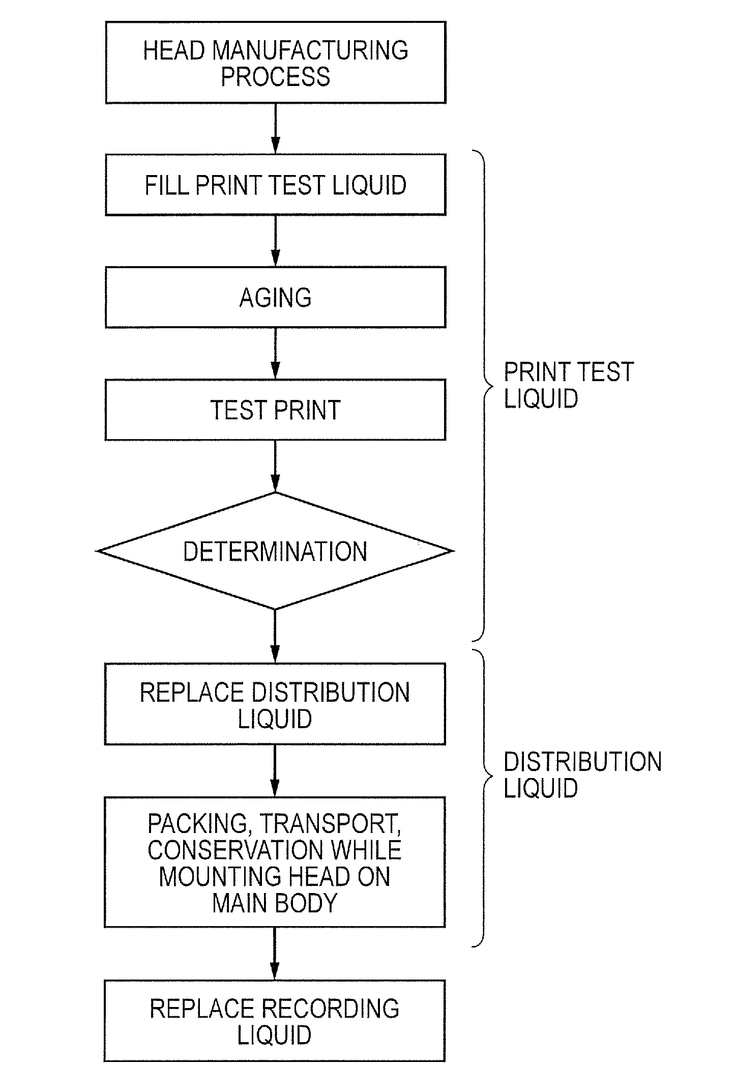
[0041]The present invention is hereinafter described in detail. It should be noted that the present invention is not limited to the following embodiments and includes all the subject matters including the matters specifying the invention. It should be noted that the term “distribution” as used herein refers to a general distribution process of a product from a producer (manufacturer) to a consumer (user) and includes all the steps from the production of a product by a producer (manufacturer) to the start of the use of the product by a consumer (user), such as packing and conservation before and after transport, as well as transport.

[0042][1] Filling Liquid for Distribution:

[0043]The term “filling liquid for distribution” refers to a liquid which is to fill a nozzle flow path communicating with an ink discharge port during distribution of a thermal ink jet head. The filling liquid for distribution is caused to fill the nozzle flow path by a producer (manufacturer) prior to distributi...

example 1

[0153]C.I Food Black 2 (FB-2) was used as a dye. Glycerin was used as a water-soluble organic compound. POE (10) acetylene glycol (“Acetylenol E100” manufactured by Kawaken Fine Chemicals Co., Ltd.) was used as a nonionic surfactant. Ion-exchanged water was added to FB-2 (0.2 part by mass), glycerin (20 parts by mass), and the nonionic surfactant (0.5 part by mass) so as to obtain 100 parts by mass in total. The composition thus obtained was stirred for 2 hours, and then, the composition was filtered with a membrane filter having a pore diameter of 1 μm. The filtrate was passed through an ion exchange resin layer to remove impurities such as calcium, to thereby obtain a filling liquid for distribution of Example 1.

example 2

[0154]A filling liquid for distribution of Example 2 was obtained in the same way as in Example 1 except for changing the addition amount of FB-2 to 0.4 part by mass.


PUM


Abstract

A filling liquid for distribution of an ink jet head of a thermal type, the filling liquid filling a nozzle flow path during distribution of the ink jet head, a hydrophilic region formed on a periphery of an ink discharge port having an opening area of from 100 to 350 μm2, the filling liquid including: an aqueous medium having at least a water-soluble organic compound and water as constituents; and a dye dissolved in the aqueous medium, a concentration of the dye in the filling liquid being 0.2 mass % or more and 1 mass % or less with respect to a total mass of the filling liquid and the concentration of the dye being equal to or less than saturation solubility with respect to the water-soluble organic compound, wherein the filling liquid has a surface tension of 25 mN / m or more and 34 mN / m or less.

Description

BACKGROUND OF THE INVENTION[0001]1. Field of the Invention[0002]The present invention relates to a filling liquid for distribution, which is to fill a nozzle flow path communicating with an ink discharge port during distribution of a thermal ink jet recording head (ink jet head), to an ink jet head using the filling liquid for distribution, and to a distribution method for the ink jet head.[0003]2. Description of the Related Art[0004]Hitherto, as a thermal ink jet head, there has been known an ink jet head having a structure in which a plurality of nozzle flow paths partitioned by nozzle walls are formed, a plurality of ink discharge ports communicating with the nozzle flow paths are formed, and a heater is disposed in each nozzle flow path. The ink jet head having the above-mentioned structure has a mechanism in which ink filling the inside of each nozzle flow path is heated by a heater to make the ink bubble (foam) to fly liquid droplets of ink from the ink discharge ports.[0005]T...

Claims


Application Information

Patent Timeline
Patent Type & Authority Applications(United States)
IPC IPC(8): B41J2/175
CPCB41J2/175B41J2/17563B41J2/17509B41J2/17533C09D11/328
Inventor HIMURA, ERIKOSUZUKI, SHINTAROSUMIKAWA, YUSUKETSUTSUI, TAKAHIROKOIKE, SHOJI
Owner COPYER
Why Eureka
Try Eureka