Liquid crystal display device and television receiver

a technology which is applied in the field of liquid crystal display device and television receiver, can solve the problems of increased cost of preparing a large number of light emitting diodes, a high temperature of leds, and a high material cost of the substrate, so as to achieve easy expansion, easy dispersion, and easy ensuring of the area of the connection plate

Active Publication Date: 2014-10-23
PANASONIC INTELLECTUAL PROPERTY CORP OF AMERICA
View PDF10 Cites 30 Cited by
  • Summary
  • Abstract
  • Description
  • Claims
  • Application Information

AI Technical Summary

Benefits of technology

[0035]According to the implementations described above, in the liquid crystal display device including the backlight unit for irradiating the entire image formation region with light of the light emitting diodes arranged in a concentrated manner, the heat generated from the light emitting diode can be efficiently dissipated.
[0043]In the circuit board, temperature becomes particularly higher in the vicinity of a terminal of the LED, and heat spreads in a concentric manner. According to the implementations described above, it is possible to increase the radius of a circle that can be drawn on the connection plate and is centered at the terminal of the LED. Consequently, the heat of the LED can be further efficiently released.

Problems solved by technology

This increases cost for preparing a large number of light emitting diodes as well as a material cost of the substrate on which the light emitting diodes are to be arranged.
This structure, however, needs to increase the arrangement density of the LEDs, and hence temperature of the LEDs is liable to be high.
Alternatively, depending on the size of the liquid crystal display device, it is sometimes necessary to arrange the light emitting diodes in two or more rows, because a sufficient amount of light for illuminating the entire image formation region cannot be obtained by simply arranging the light emitting diodes linearly in one row.

Method used


Image

  • Liquid crystal display device and television receiver
  • Liquid crystal display device and television receiver
  • Liquid crystal display device and television receiver

Examples


first embodiment

[0076]Now, the present application is described below with reference to the accompanying drawings.

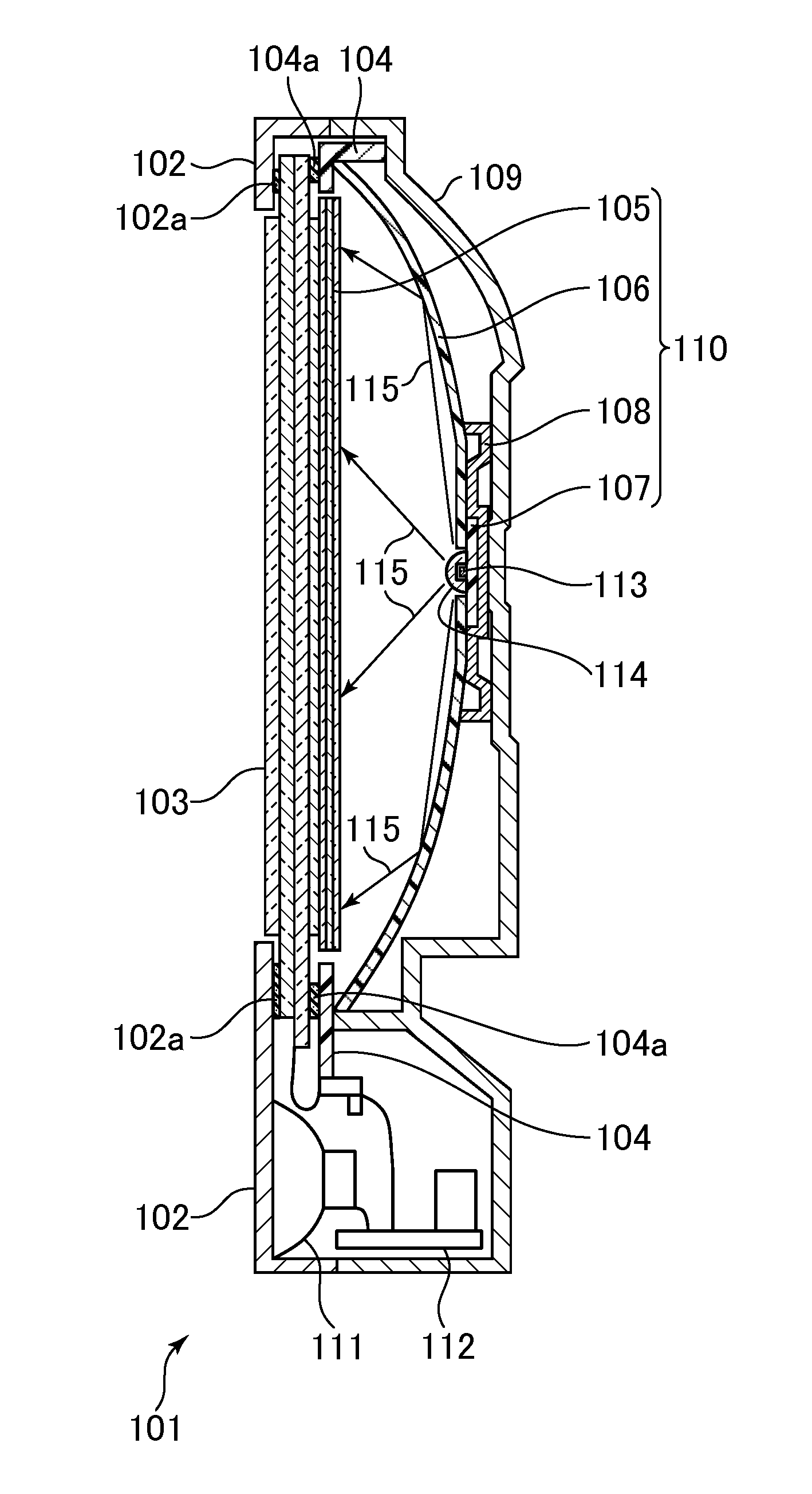
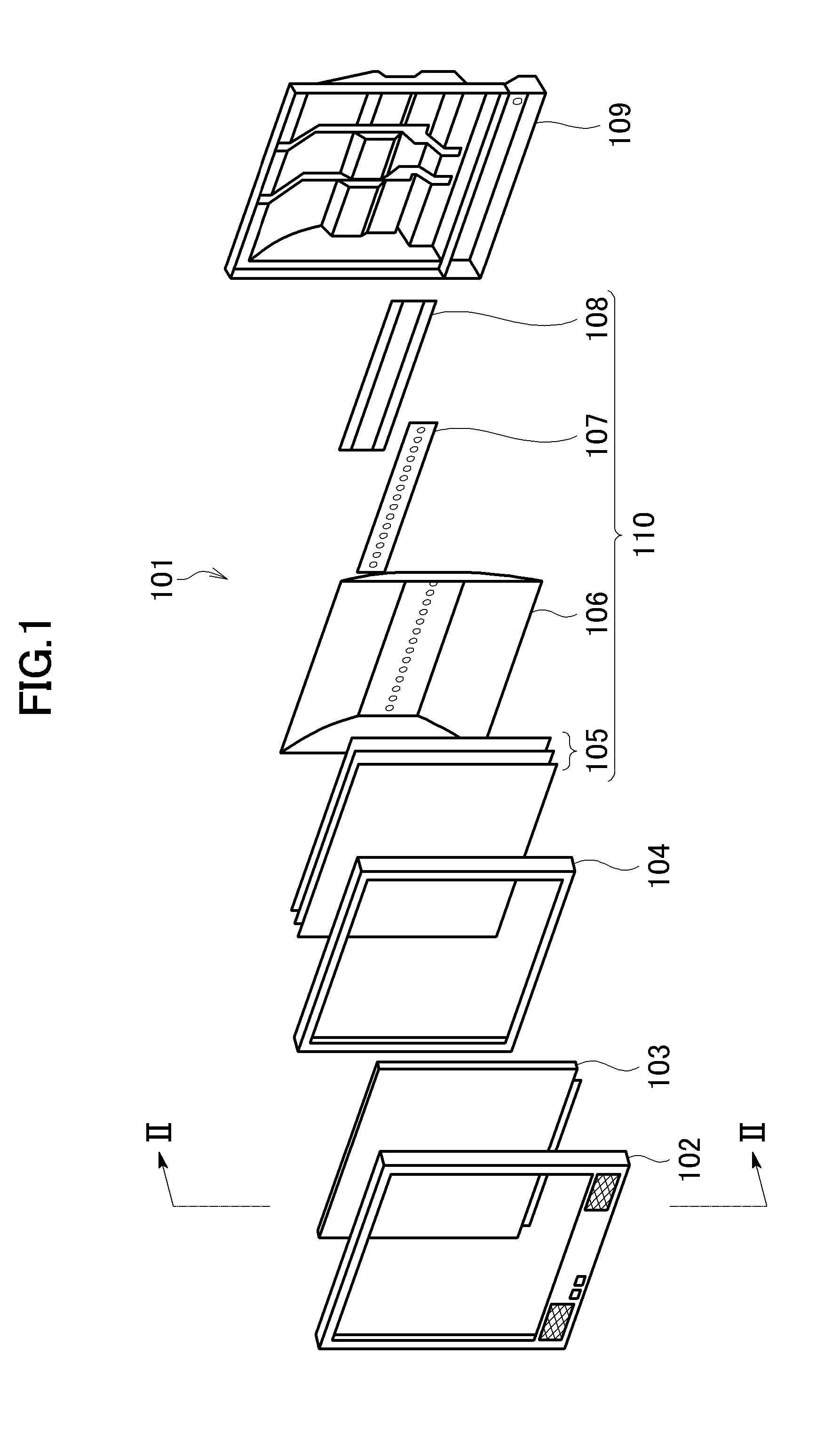
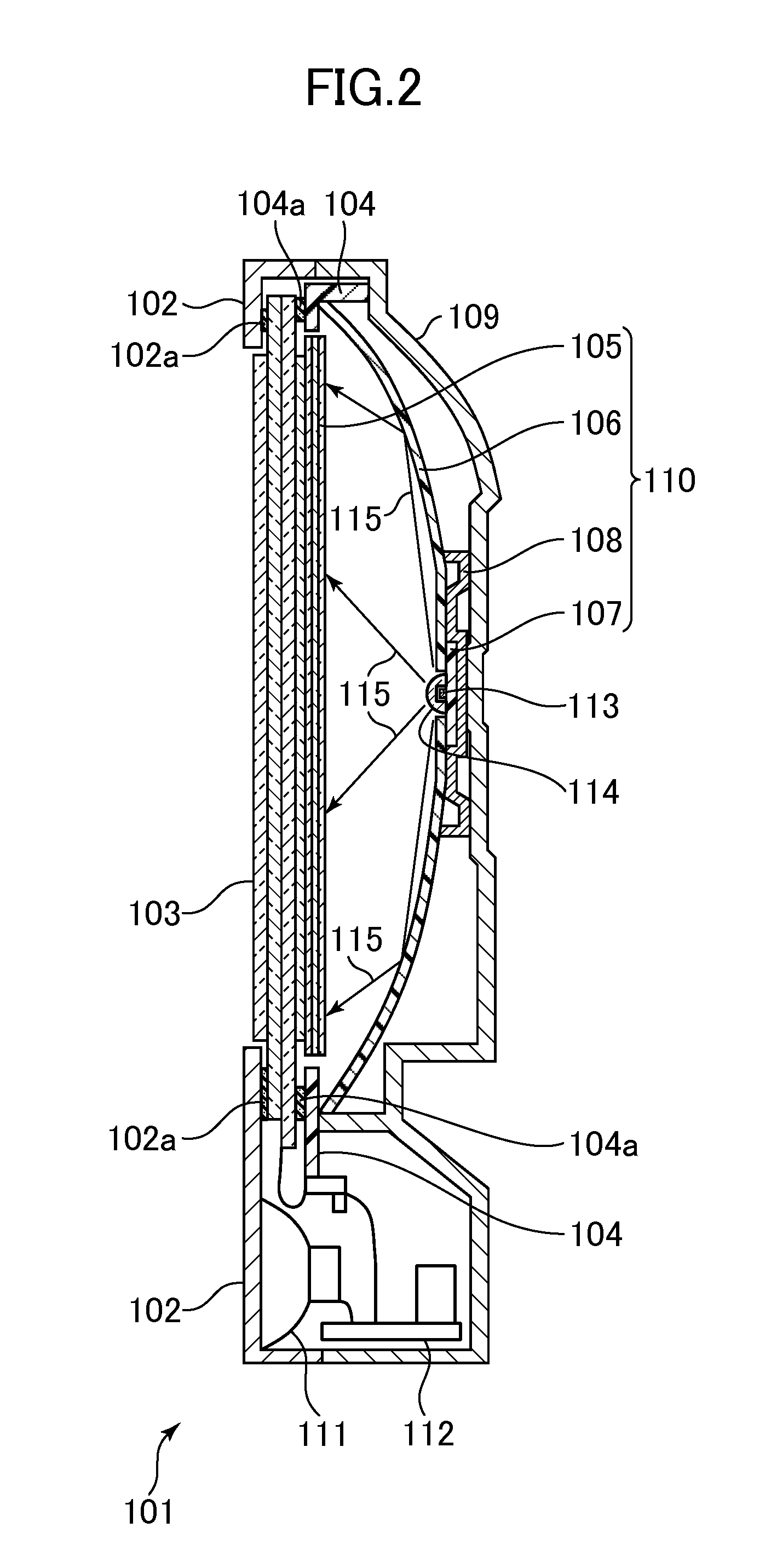
[0077]FIG. 1 is an exploded perspective view of a liquid crystal display device 101 according to this embodiment. As illustrated in FIG. 1, the liquid crystal display device 101 is assembled by arranging, in order from the front side, an upper frame 102, a liquid crystal panel 103, an intermediate frame 104, an optical sheet group 105, a reflection sheet 106, a light emitting diode substrate 107, a radiator plate 108, and a lower frame 109. Note that, the optical sheet group 105, the reflection sheet 106, the light emitting diode substrate 107, and the radiator plate 108 together construct a backlight unit 110 that functions as a planar light source for illuminating the liquid crystal panel 103 from the rear surface side thereof. FIG. 1 illustrates only structural components of the liquid crystal display device 101 and omits other components, such as a control board and a speaker.

[0078]...

second embodiment

[0112]Subsequently, the present application is described with reference to the accompanying drawings.

[0113]FIG. 10 is an exploded perspective view of a liquid crystal display device 201 according to this embodiment. As illustrated in FIG. 10, the liquid crystal display device 201 is assembled by arranging, in order from the front side, an upper frame 202, a liquid crystal panel 203, an intermediate frame 204, an optical sheet group 205, a reflection sheet 206, a light emitting diode substrate 207, a radiator plate 208, and a lower frame 209. Note that, the optical sheet group 205, the reflection sheet 206, the light emitting diode substrate 207, and the radiator plate 208 together construct a backlight unit 210 that functions as a planar light source for illuminating the liquid crystal panel 203 from the rear surface side thereof. FIG. 10 illustrates only structural components of the liquid crystal display device 201 and omits other components, such as a control board and a speaker....

third embodiment

[0152]Further, the present application is described with reference to the accompanying drawings. FIG. 19 is a schematic cross-sectional view of a liquid crystal display device 301 according to this embodiment. FIG. 20 is a plan view of a backlight unit 310 included in the liquid crystal display device 301.

[0153]In the following description, y illustrated in FIG. 20 is the first direction, and x is the second direction orthogonal to the first direction. In the example described herein, the first direction y is the vertical direction of a liquid crystal display panel 320 to be described below, and the second direction x is the horizontal direction of the liquid crystal display panel 320. Note that, the first direction may be defined as the horizontal direction of the liquid crystal display panel 320, and the second direction may be defined as the vertical direction of the liquid crystal display panel 320.

[0154]As illustrated in FIG. 19, the liquid crystal display device 301 includes t...


PUM

PropertyMeasurementUnit
thicknessaaaaaaaaaa
diameteraaaaaaaaaa
areaaaaaaaaaaa

Abstract

A liquid crystal display device includes: a liquid crystal panel; a reflection sheet arranged on a rear surface side of the liquid crystal panel, the reflection sheet being curved so that a surface facing the liquid crystal panel is recessed; and a light emitting diode substrate including: a light emitting diode array in which a plurality of light emitting diodes are arranged along a longitudinal direction; and electrodes connected to the plurality of light emitting diodes. In a circle which is centered at one light emitting diode and whose diameter is a distance from the one light emitting diode to another light emitting diode adjacent to the one light emitting diode, an area of the electrode connected to a high temperature side electrode of the one light emitting diode is larger than an area of the electrode connected to a low temperature side electrode of the one light emitting diode.

Description

CROSS-REFERENCE TO RELATED APPLICATION[0001]This application is Bypass Continuation of international patent application PCT / JP2012 / 063940 filed on May 30, 2012 designating the United States of America, the entire disclosure of which is incorporated herein by reference. Priority is claimed based on Japanese patent application JP2011-186080 filed on Aug. 29, 2011; Japanese application JP2011-186081 filed on Aug. 29, 2011; Japanese application JP2011-186082 filed on August 29. The entire disclosure of Japanese patent applications JP2011-186080, JP2011-186081, JP2011-186082 are incorporated herein by reference in their entirety.TECHNICAL FIELD[0002]The present application relates to a liquid crystal display device including a backlight unit that uses LEDs as light sources, and a television receiver including the liquid crystal display device. In particular, the present application relates to a technology for improving heat dissipation performance for LEDs.BACKGROUND[0003]Japanese Patent...

Claims


Application Information

Patent Timeline
Patent Type & Authority Applications(United States)
IPC IPC(8): G02F1/1335G09G3/36
CPCG02F1/133603G02F2001/133612G09G3/36G02F1/133605G02F1/133613G02F1/133612G02F1/133628G02B6/0011
Inventor IMAJO, IKUKO
Owner PANASONIC INTELLECTUAL PROPERTY CORP OF AMERICA
Why Eureka
Try Eureka