Flow manipulating arrangement for a turbine exhaust diffuser

a technology of turbine exhaust and flow control, which is applied in the direction of machines/engines, stators, liquid fuel engines, etc., can solve problems such as inefficiency

Inactive Publication Date: 2014-10-23
GENERAL ELECTRIC CO
View PDF17 Cites 32 Cited by
  • Summary
  • Abstract
  • Description
  • Claims
  • Application Information

AI Technical Summary

Benefits of technology

[0020]FIG. 12 is a schematic illustration of a control mechanism of the flow manipulation arrangement of FIG. 10; and

Problems solved by technology

Inefficiency is due, at least in part, to flow separation on exhaust diffuser components, such as walls and struts, for example.

Method used


Image

  • Flow manipulating arrangement for a turbine exhaust diffuser
  • Flow manipulating arrangement for a turbine exhaust diffuser
  • Flow manipulating arrangement for a turbine exhaust diffuser

Examples


Embodiment Construction

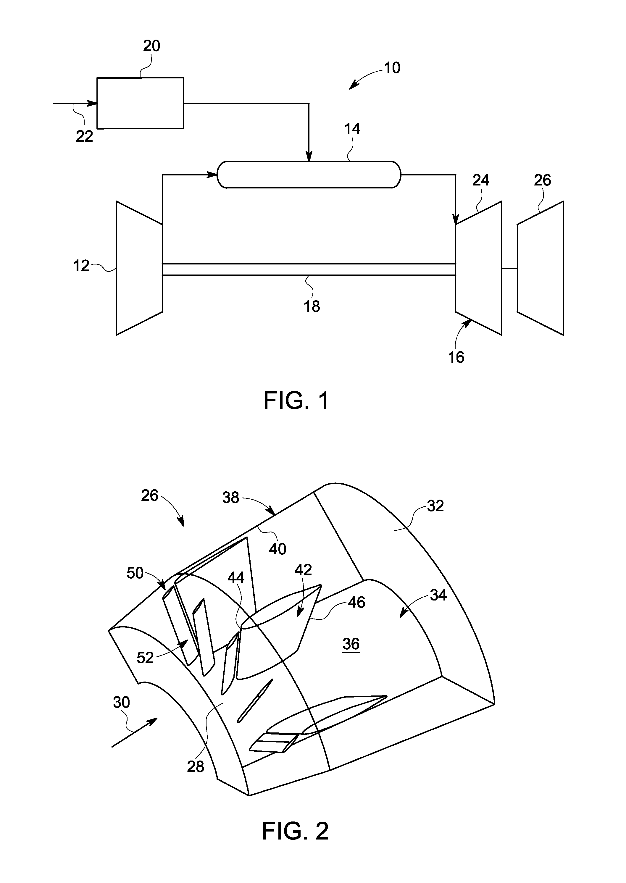
[0023]Referring to FIG. 1, a turbine system, such as a gas turbine system, for example, is schematically illustrated with reference numeral 10. The turbine system 10 includes a compressor section 12, a combustor section 14, a turbine section 16, a shaft 18 and a fuel nozzle 20. It is to be appreciated that one embodiment of the turbine system 10 may include a plurality of compressors 12, combustors 14, turbines 16, shafts 18 and fuel nozzles 20. The compressor section 12 and the turbine section 16 are coupled by the shaft 18. The shaft 18 may be a single shaft or a plurality of shaft segments coupled together to form the shaft 18.

[0024]The combustor section 14 uses a combustible liquid and / or gas fuel, such as natural gas or a hydrogen rich synthetic gas, to run the turbine system 10. For example, fuel nozzles 20 are in fluid communication with an air supply and a fuel supply 22. The fuel nozzles 20 create an air-fuel mixture, and discharge the air-fuel mixture into the combustor se...


PUM


Abstract

A flow manipulating arrangement for a turbine exhaust diffuser includes a strut having a leading edge and a trailing edge, the strut disposed within the turbine exhaust diffuser. Also included is a plurality of rotatable guide vanes disposed in close proximity to the strut and configured to manipulate an exhaust flow, wherein the plurality of rotatable guide vanes is coaxially aligned and circumferentially arranged relative to each other. Further included is an actuator in operative communication with the plurality of rotatable guide vanes and configured to actuate an adjustment of the plurality of rotatable guide vanes. Yet further included is a circumferential ring operatively coupling the plurality of rotatable guide vanes, wherein the actuator is configured to directly actuate rotation of one of the rotatable guide vanes, and wherein the circumferential ring actuates rotation of the plurality of rotatable guide vanes upon rotational actuation by the actuator.

Description

BACKGROUND OF THE INVENTION[0001]The subject matter disclosed herein relates to turbine systems, and more particularly to boundary layer flow control of turbine exhaust diffuser components.[0002]Typical turbine systems, such as gas turbine systems, for example, include an exhaust diffuser coupled to a turbine section of the turbine system to increase efficiency of a last stage bucket of the turbine section. The exhaust diffuser is geometrically configured to rapidly decrease the kinetic energy of flow and increase static pressure recovery within the exhaust diffuser.[0003]Commonly, the exhaust diffuser is designed for full load operation, however, the turbine system is often operated at part load or on a cold day. Therefore, part load performance efficiency is sacrificed, based on the full load design. Inefficiency is due, at least in part, to flow separation on exhaust diffuser components, such as walls and struts, for example. Flow separation often is caused, in part, by swirling ...

Claims


Application Information

Patent Timeline
Patent Type & Authority Applications(United States)
IPC IPC(8): F01D9/02
CPCF01D9/02F01D5/146F01D17/162F01D25/30
Inventor PAKKALA, SRINIVAS RAOCHENGAPPA, MANJUNATH BANGALOREMUNDRA, KAMLESHSADHU, ANTANUSAKEKAR, KUNAL UPENDRASUBRAMANIYAN, MOORTHIWICHMANN, LISA ANNE
Owner GENERAL ELECTRIC CO
Why Eureka
Try Eureka