Standard antenna interface

a technology of antenna interface and standard antenna, which is applied in the direction of machine supports, coupling device connections, mechanical equipment, etc., can solve the problems of introducing opportunities for installation errors, reducing the performance of the radio network, and complex and time-consuming installations

Active Publication Date: 2014-10-23
COMMSCOPE TECH LLC
View PDF2 Cites 31 Cited by
  • Summary
  • Abstract
  • Description
  • Claims
  • Application Information

AI Technical Summary

Benefits of technology

[0011]The RF interconnection module may include a float plate disposed in the housing. The capacitive coupling may be movably disposed in the float plate so that the capacitive coupling may move with respect to the housing. The float plate may be made of an elastomer material. The float plate may include a plurality of flexibly fingers that define an aperture for receiving the capacitive coupling. The flexible fingers may operate to movably secure the capacitive coupling in the aperture.

Problems solved by technology

Such an installation decreases the performance of the radio network, creates complex and time consuming installations, and introduces opportunities for installation errors.
Jumper cables present RF losses and Passive Intermodulation products (PIM) performance issues.
These issues degrade network performance, and add significant cost to the network operator to overcome.
Jumper cables also require more weatherproofing, and additional capital expense and operating expense.
This can result in installation errors, missing hardware, wrong cable lengths, and inadequate mounting hardware.
This introduces the possibility of installing cables at the wrong locations, improperly assembling connectors to the jumper cables, or not engaging them correctly.
Integrated antennas do not provide flexibility for the network operator to select different RRHs or Antennas from different suppliers.
The radio network operator is limited to the supplier of the active or integrated antenna and the performance and price of that system.
The Integrated antenna approach also restricts the ability of the operator to leverage supplier diversity for the antenna products, or for the RRH units.
It also limits the availability of new beamwidth antennas, as well as multi-beam antennas.
The operator is further challenged to stock spares of expensive combined units.
Thus, integrating an antenna and RRH in a single unit on the tower would require antennas to be replaced at the same rate as RRH's, increasing operating expenses.
Additionally, current installations are not visibly appealing due to non-standard mounting configurations and the use of multiple jumper cables.
Such installations do not have the appearance of a well thought out solution.

Method used


Image

  • Standard antenna interface
  • Standard antenna interface
  • Standard antenna interface

Examples


Embodiment Construction

OF THE INVENTION

[0036]A Standard Antenna Interface is described herein to overcome the limitations of a traditional RRH and antenna tower top installation. This invention creates a standard antenna interface that provides a reduced installation time, prevents the installer from directly touching / interfacing with the RF electrical path, creates a PIM free interface, and allows the network operator the flexibility to select any brand of antenna or RRH to install. This solution further enables the stocking of separate antennas and RRH's, thus reducing the cost of inventory. In addition, the higher failure rate RRH's can be replaced independently of the more reliable passive antennas.

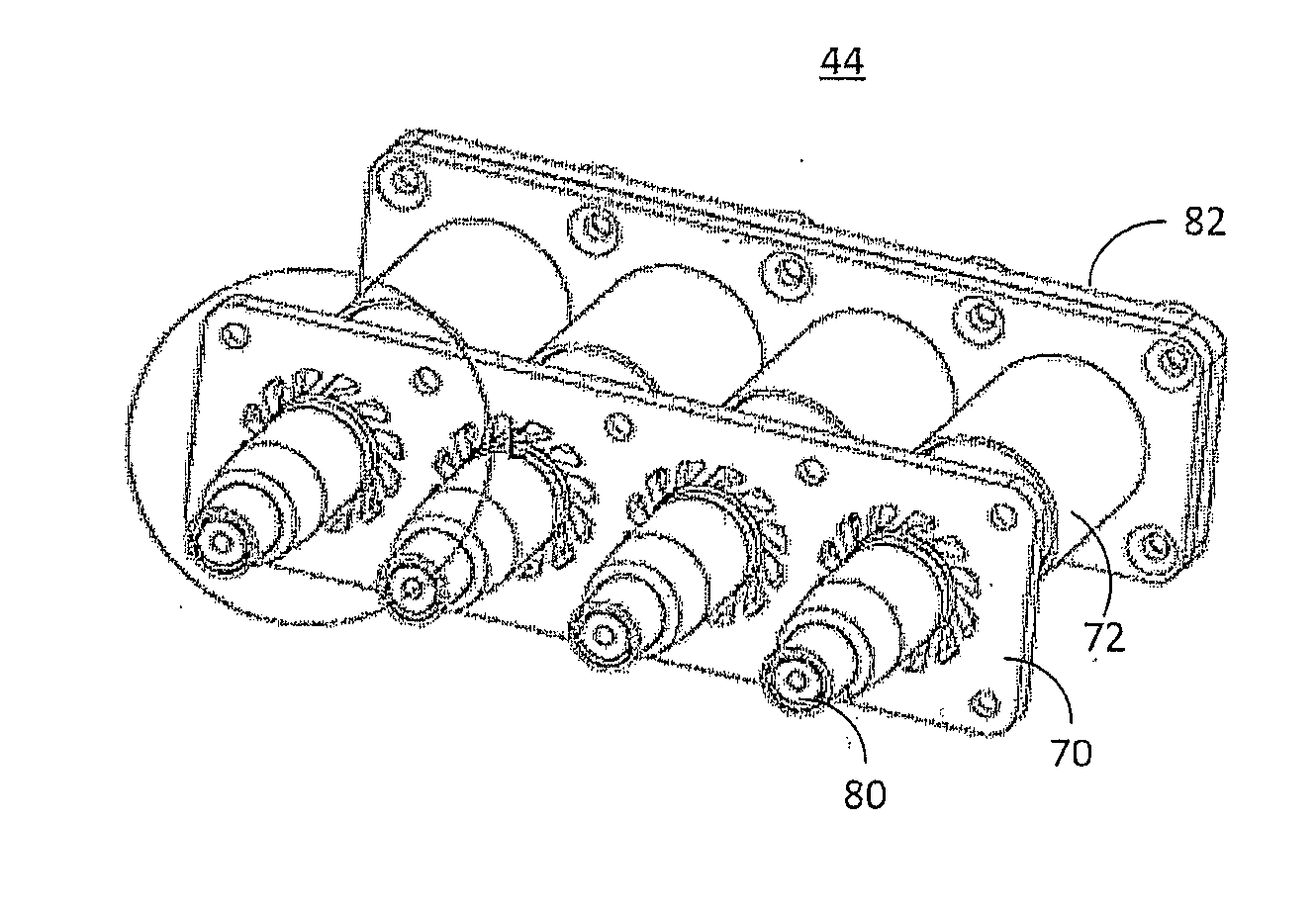
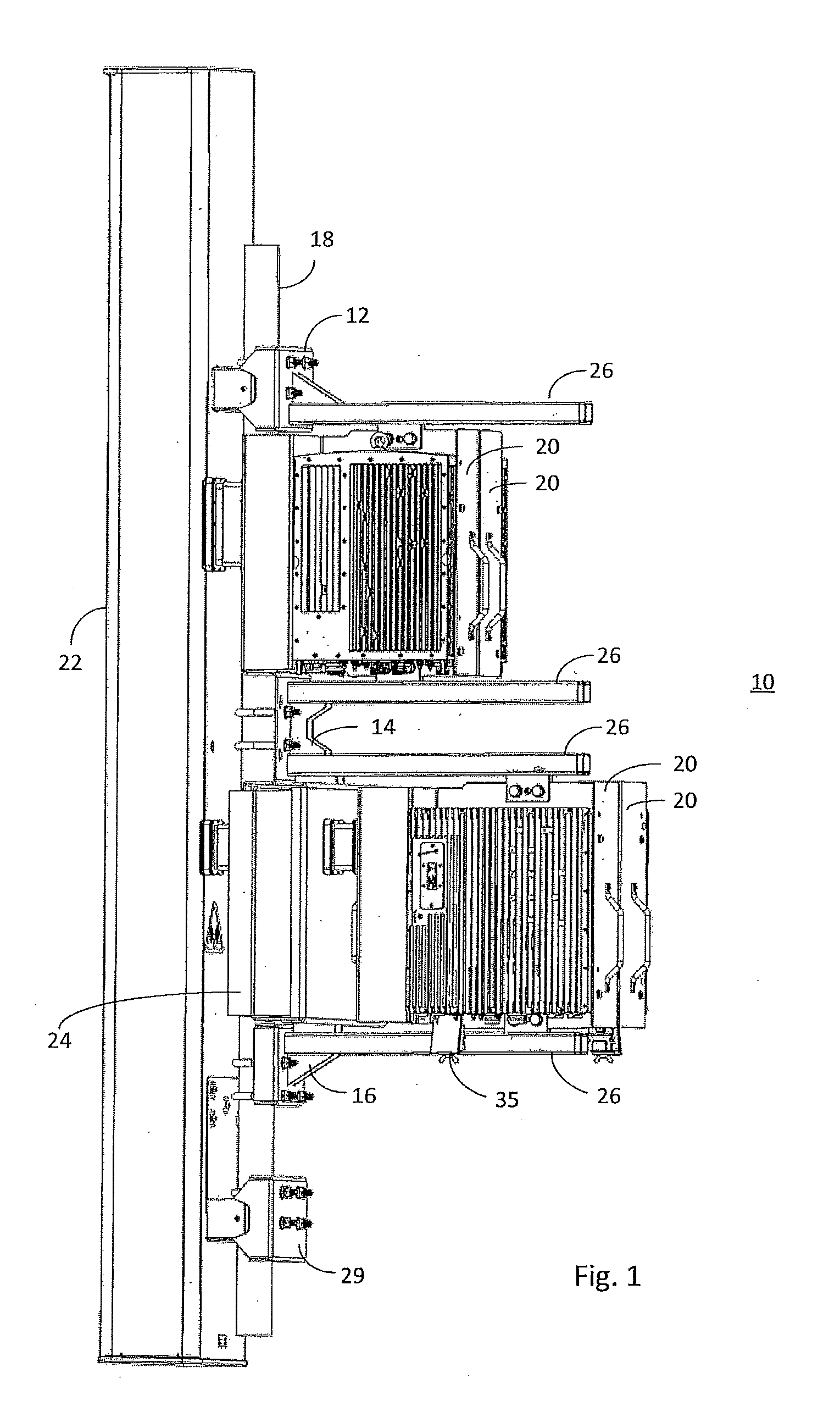
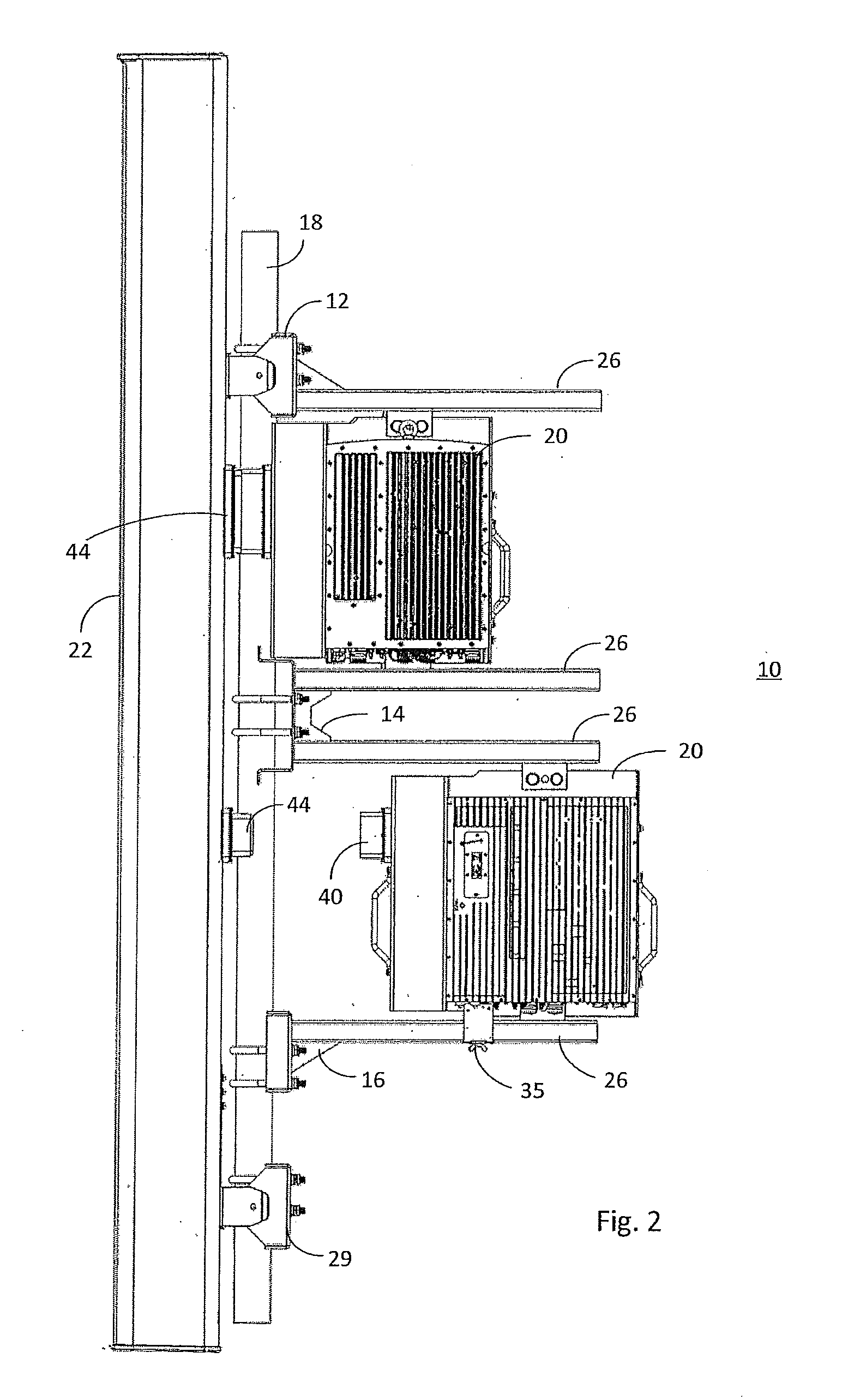
[0037]The Standard Antenna Interface comprises of a standard interface structure, including antenna mounting brackets and RRH mounting structure, and a RF interconnection module. The standard interface structure acts as the mounting medium for both the antenna and the RRH. Both the antenna and RRH are mount...


PUM


Abstract

An RF interconnection module includes a housing having a perimeter, a capacitive coupling, and a float gasket disposed about the perimeter of the housing. When the housing is mounted in an opening, the float gasket is positioned between the housing and the opening. The float gasket may be made of an elastomer material and may include a plurality of outwardly extending ribs for movable securing the gasket in the opening. In addition, a mount assembly includes a bracket assembly attachable to a tower-mounted equipment and at least one jumper cable having at least one ohmic connector for connecting to the tower-mounted equipment and at least one capacitive connector. The capacitive connector may comprise an RF interconnection module mounted on the bracket assembly. The bracket assembly may be adjustable to accommodate tower mounted equipment of various sizes.

Description

[0001]This application is a continuation in part of and claims priority to U.S. application Ser. No. 14 / 137,059, filed Dec. 20, 2013. This application also claims priority to the following U.S. Provisional Applications, pursuant to 35 U.S.C. §120: U.S. Provisional Application Ser. No. 61 / 907,259, filed 21 Nov. 2013; U.S. Provisional Application Ser. No. 61 / 863,739, filed 8 Aug. 2013. The disclosures of these applications also are incorporated by reference.BACKGROUND[0002]The present inventions relate generally to wireless communications. In particular, they relate to improvements in wireless base station antenna and radio deployments.[0003]A traditional installation of a wireless radio network system mounted at the top of the tower consists of a remote radio head (RRH) and a separate antenna. These components are mounted in separate locations and are cabled together using jumper cables to pass the radio frequency (RF) signal between them. Such an installation decreases the performan...

Claims


Application Information

Patent Timeline
Patent Type & Authority Applications(United States)
IPC IPC(8): H01R13/46
CPCH01R13/46H01Q1/1228H01Q1/246H01R2103/00H01R13/518H01R13/6315H01R13/748H01R24/52H01R2201/02H01R25/006E04H12/00F16M13/02H01R13/73
Inventor COLAPIETRO, JULIAN R.BUONDELMONTE, CHARLES J.BONCZYK, MICHAEL F.DONALDSON, JR., JIMMIE L.KURK, MORGAN C.BUTLER, RAY K.SCHMUTZLER, STEVEN LEEDICKERSON, CALVIN
Owner COMMSCOPE TECH LLC
Why Eureka
Try Eureka