Spring, Belt Tensioning Device, and Assembly

a belt tensioning device and belt tensioning technology, which is applied in the direction of belt/chain/gearing, mechanical equipment, wound springs, etc., can solve the problems of increased wear, difficult mounting of belts, and limited installation space around the generator axis as well as before and behind the belt plane, etc., to achieve compact design, convenient mounting, and compact construction

Active Publication Date: 2014-10-23
MUHR UND BENNDER KG
View PDF3 Cites 41 Cited by
  • Summary
  • Abstract
  • Description
  • Claims
  • Application Information

AI Technical Summary

Benefits of technology

[0007]The present invention is based on the object, to propose a spring, which is compactly constructed and thus especially suitable for the use in a belt tensioning device. The object is further, to propose a belt tensioning device for a belt drive, which is compact in design, easily mounta

Problems solved by technology

The available installation space around the generator axis as well as before and behind the belt plane is especially limited for two tensioning devices or a double arm tensioning device.
Furthermore, the mounting of t

Method used


Image

  • Spring, Belt Tensioning Device, and Assembly
  • Spring, Belt Tensioning Device, and Assembly
  • Spring, Belt Tensioning Device, and Assembly

Examples


Embodiment Construction

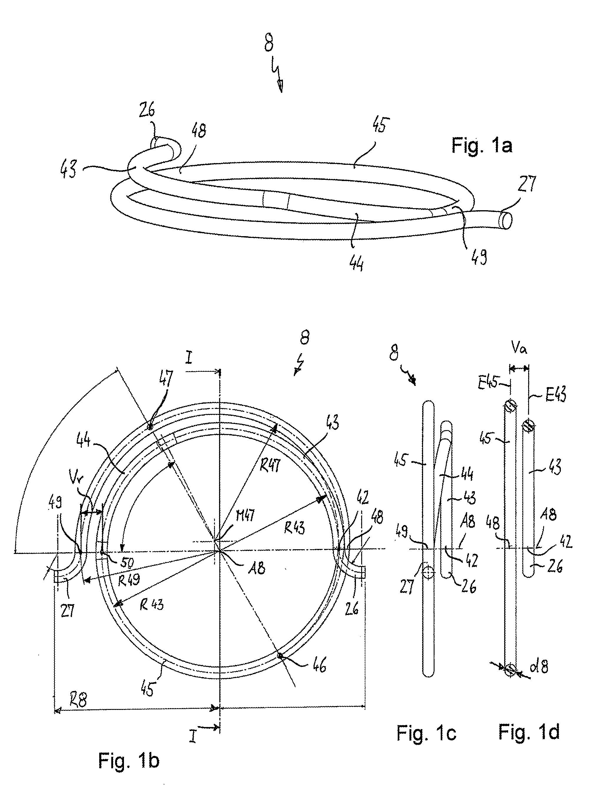
[0038]FIGS. 1a) to 1d), which are commonly described in the following, show a spring 8 according to the invention in a first embodiment. The spring 8 has approximately 1.5 coils, or windings. In other words, the spring extends across 540° around the spring axis A8, wherein also any other number of coils between a minimum of 1.25 and a maximum of 2.5 (450° and 900°) may be considered. The spring 8 has, starting from a first end portion 26, bent radially outward, a first coil portion 43, which extends in a plane E43 with a constant radius R43 over an angle range of approximately 110° to 120° around the spring axis A8. A coil portion means, that the spring is wound in this portion around the spring axis with a concave inner curvature. The plane E43 which is defined by the first coil portion 43, is arranged substantially at a right angle to the spring axis A8. The first coil portion 43 without an incline is followed by a transition—or incline portion 44, which extends across an angle ra...


PUM


Abstract

A spring, especially for use in a belt tensioning device, with a number of at least 1.25 and at a maximum 2.5 coils, which extend around a spring axis A8, wherein a first coil end 42 has an axial offset Va relative to a first coil region 48, arranged at an angle of 360° around the spring axis A8, and wherein a second coil end 49 has an radial offset Vr relative to a second coil region 50 arranged at an angle of 360° around the spring axis A8. A belt tensioning device and an assembly with such a belt tensioning device include such a spring.

Description

BACKGROUND OF THE INVENTION[0001]This invention relates to a belt tensioning device for a belt drive, which comprises a continuous belt and at least two belt pulleys, of which one serves as a drive and one as an output of the belt drive. Such belt drives are especially used in combustion engines of a motor vehicle for driving auxiliary units, wherein a first belt pulley rests on the crank shaft of the combustion engine and drives the belt. Further belt pulleys are assigned to the auxiliary units, as for example a water pump, an electric generator or an air conditioning compressor and are rotatably driven by the belt drive. In common belt drives, the auxiliary units are designed as consumers, which means, they are driven by the belt pulley of the crank shaft via the belt. In this case, the undriven side of the belt is arranged between the crank shaft and the unit following in circumferential direction of the belt, generally the generator. To ensure a sufficient contact of the belt ar...

Claims


Application Information

Patent Timeline
IPC IPC(8): F16H7/12F16F1/04
CPCF16F1/04F16H7/12F16F1/14F16H7/1218F16H7/1281F16H2007/081F16H2007/0874F16H2007/0893
Inventor ZACKER, MATTHIASJUD, JOACHIMPFEIFER, SIMONJUNG, MANFRED
Owner MUHR UND BENNDER KG
Why Eureka
Try Eureka