Parylene-based microelectrode array implant for spinal cord stimulation

a microelectrode array and spinal cord technology, applied in the field of implantable electrode arrays, can solve the problem that none of these designs has been successfully implanted chronically

a microelectrode array and spinal cord technology, applied in the field of implantable electrode arrays, can solve the problem that none of these designs has been successfully implanted chronically

US20140316503A1Active Publication Date: 2014-10-23CALIFORNIA INST OF TECH +2

Image

  • Parylene-based microelectrode array implant for spinal cord stimulation
  • Parylene-based microelectrode array implant for spinal cord stimulation
  • Parylene-based microelectrode array implant for spinal cord stimulation

Examples


Embodiment Construction

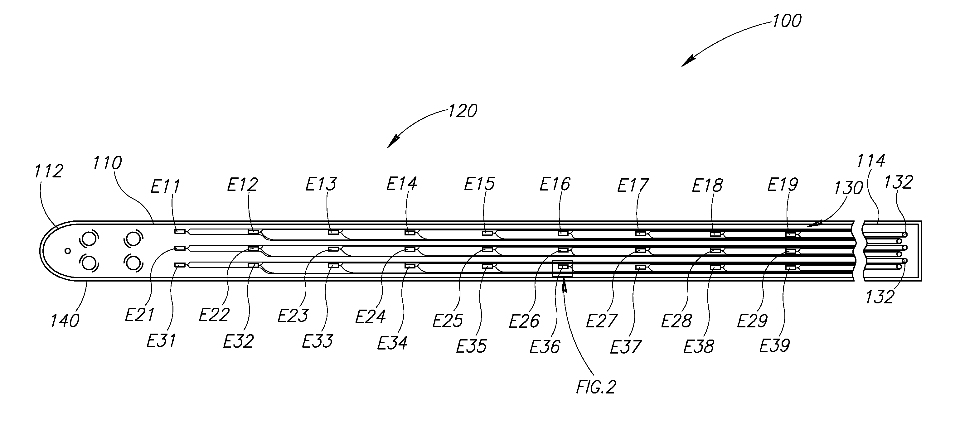
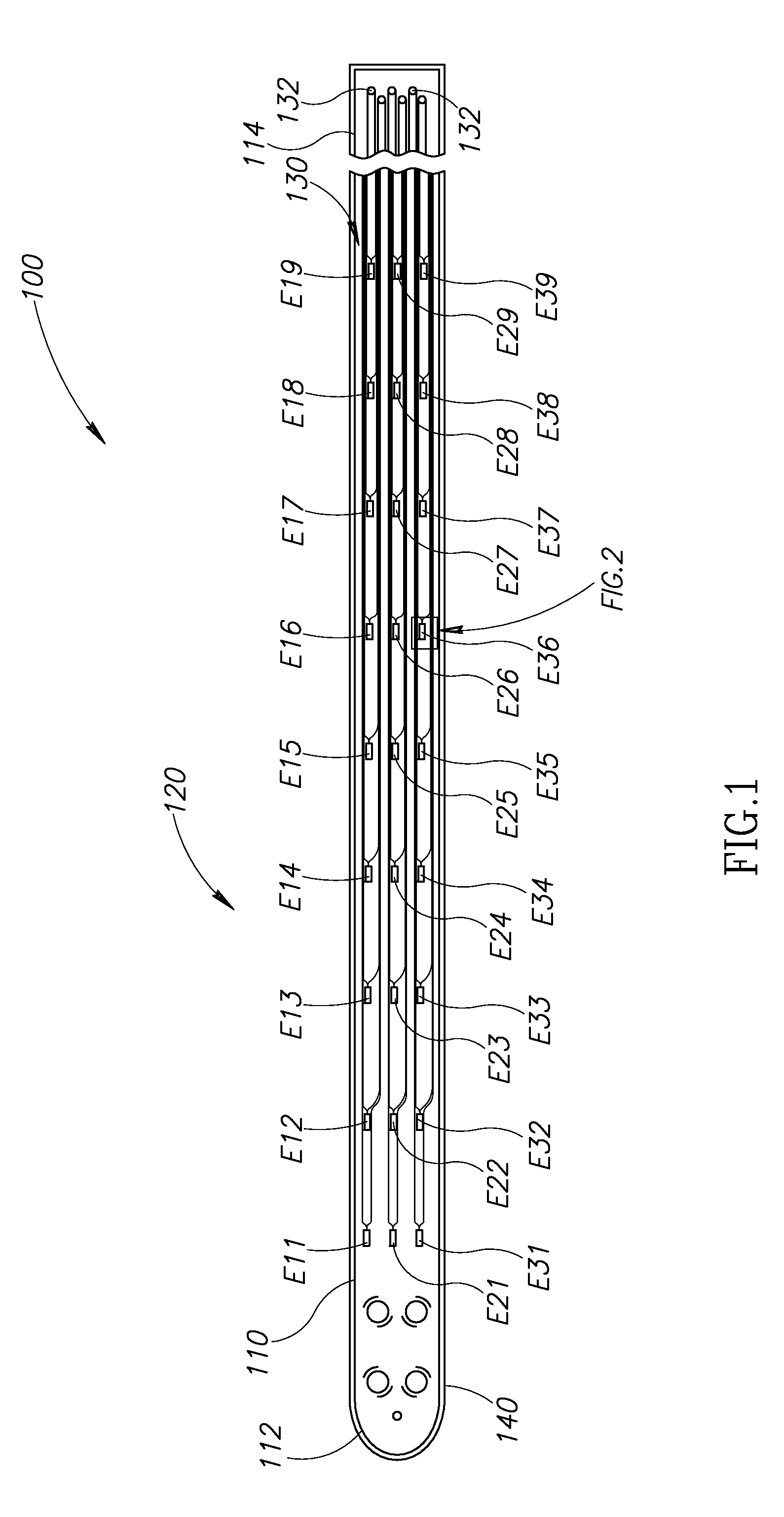
[0032]FIG. 1 illustrates an implantable electrode array assembly 100. While the embodiment of the assembly 100 illustrated is configured for implantation in a rat 500 (see FIG. 5A), embodiments may be constructed for use in other subjects, such as other mammals, including humans, and such embodiments are within the scope of the present teachings. The assembly 100 is for use with a subject that has a spinal cord 330 (see FIG. 3) with at least one selected spinal circuit (not shown) and a neurologically derived paralysis in a portion of the subject's body. By way of a non-limiting example, the assembly 100 may be implanted epidurally along the spinal cord 330. The assembly 100 may be positioned at one or more of a lumbosacral region, a cervical region, and a thoracic region of the spinal cord 330.

[0033]By way of non-limiting examples, when activated, the selected spinal circuit may (a) enable voluntary movement of muscles involved in at least one of standing, stepping, reaching, grasp...


PUM


Abstract

An implantable electrode array assembly configured to apply electrical stimulation to the spinal cord. A substantially electrically nonconductive layer of the device has a first portion positionable alongside the spinal cord that includes a plurality of first openings. The layer has a second portion that includes a plurality of second openings. Electrodes and traces are positioned inside a peripheral portion of a body portion of the device and alongside the layer. At least one of the first openings is adjacent each of the electrodes to provide a pathway through which the electrode may provide electrical stimulation to the spinal cord. At least one of the second openings is adjacent each of the traces to provide a pathway through which the trace may receive electrical stimulation. At least one trace is connected to each electrode and configured to conduct electrical stimulation received by the trace(s) to the electrode.

Description

CROSS REFERENCE TO RELATED APPLICATION(S)[0001]This application is a divisional of U.S. patent application Ser. No. 13 / 946,338, filed Jul. 19, 2013, which is a continuation of International Application PCT / US2012 / 022257, filed Jan. 23, 2012, and that International Application was published under PCT Article 21(2) in English, all of which are incorporated herein by reference in their entirety. This application also claims the benefit of U.S. Provisional Application No. 61 / 435,188, filed Jan. 21, 2011, which is incorporated herein by reference in its entirety.STATEMENT REGARDING FEDERALLY SPONSORED RESEARCH OR DEVELOPMENT[0002]This invention was made with Government support under Grant No. W81XWH-09-2-0024, awarded by the United States Army, Medical Research and Materiel Command; and Grant No. EB076151, awarded by the National Institutes of Health. The Government has certain rights in this invention.BACKGROUND OF THE INVENTION[0003]1. Field of the Invention[0004]The present invention ...

Claims


Application Information

Patent Timeline
23 Oct 2014
Publication
US20140316503A1
IPC
A61N1/05
CPC
A61N1/0551; A61N1/0553; A61N1/0558; A61N1/36062; A61N1/36067; A61N1/36128; A61N1/375; H01B5/14
Inventors
TAI, YU-CHONG; NANDRA, MANDHEEREJ S.