Turbine blade monitoring arrangement and method of manufacturing

Active Publication Date: 2014-10-30
GENERAL ELECTRIC CO
View PDF4 Cites 3 Cited by
  • Summary
  • Abstract
  • Description
  • Claims
  • Application Information

AI Technical Summary

Benefits of technology

The patent is about a turbine blade monitoring arrangement that can detect when the tips of the blades are clear of the turbine casing and when the blades are deforming. The arrangement includes a hollow component located near the blade tip, a sealing component, and a proximity sensor. The sealing component is made of a translucent material and is positioned to generate a signal through the hollow portion to the blade tip. This arrangement can provide accurate monitoring of the blade tips during operation.

Problems solved by technology

However, tighter tip clearances increase the risk that rotating parts will make contact with or rub against non-rotating parts during one of the engine's several operational modes, particularly considering that tip clearances generally vary based upon operating conditions.
Of course, having rotating and stationary parts rub or make contact during operation is typically undesirable because it may adversely affect various components or operating modes.
In addition, rubbing may result in increased clearances once the event that caused the rubbing passes.
However, this is undesirable because it generally allows for more leakage and thereby decreases the efficiency of the engine.
The downside of positioning the sensors in this manner is that the sensors are exposed to the extreme temperatures of the hot gas path.
Sensors that are able to withstand these conditions while providing accurate measurements are expensive.
Even so, because of the extreme conditions of the hot-gas path, these sensors can have short lifespans, which increase costs and maintenance requirements.
It will be appreciated that providing cooling air in this manner adds complexity to engine systems and decreases the efficiency of the engine.

Method used


Image

  • Turbine blade monitoring arrangement and method of manufacturing
  • Turbine blade monitoring arrangement and method of manufacturing
  • Turbine blade monitoring arrangement and method of manufacturing

Examples


Embodiment Construction

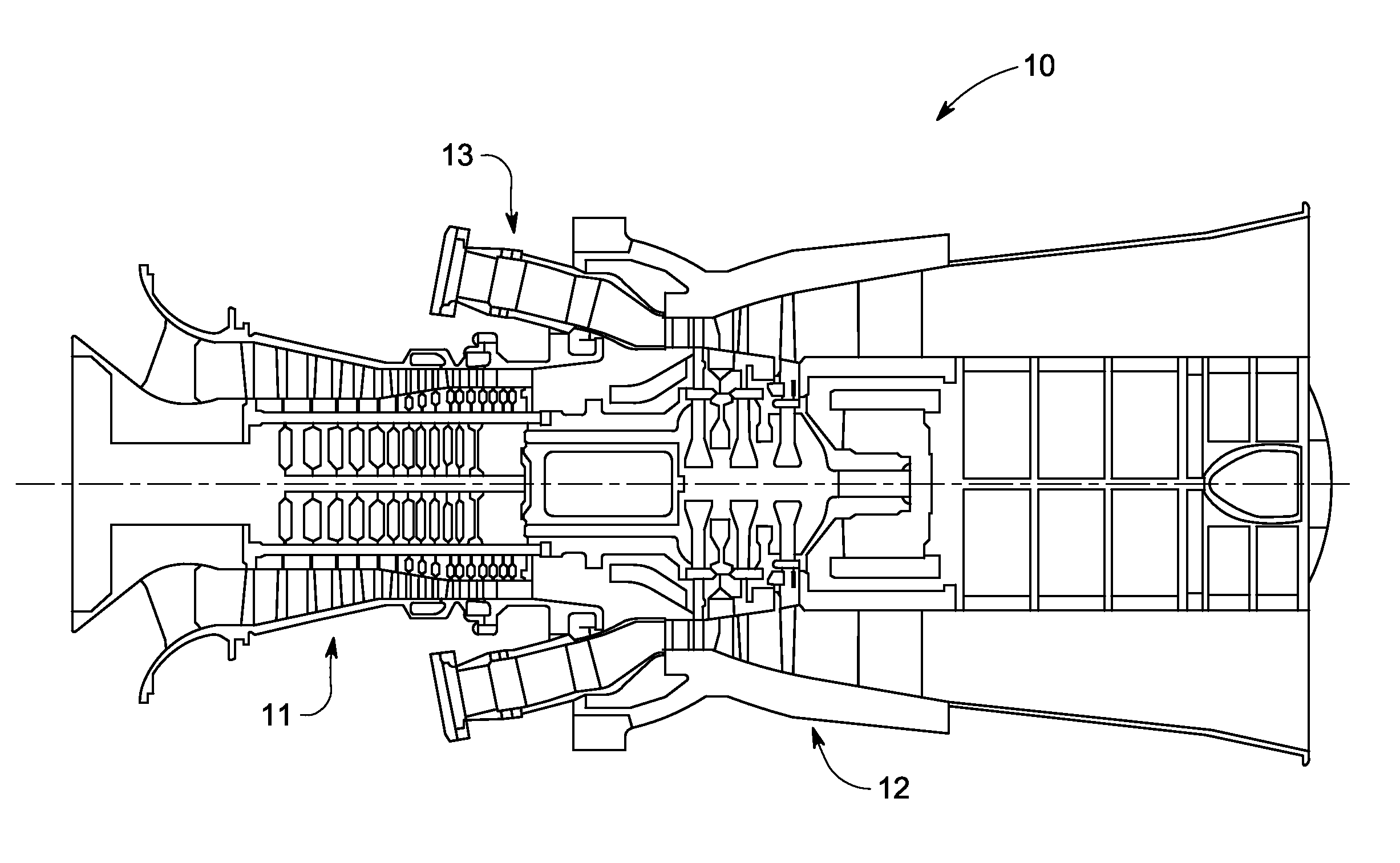
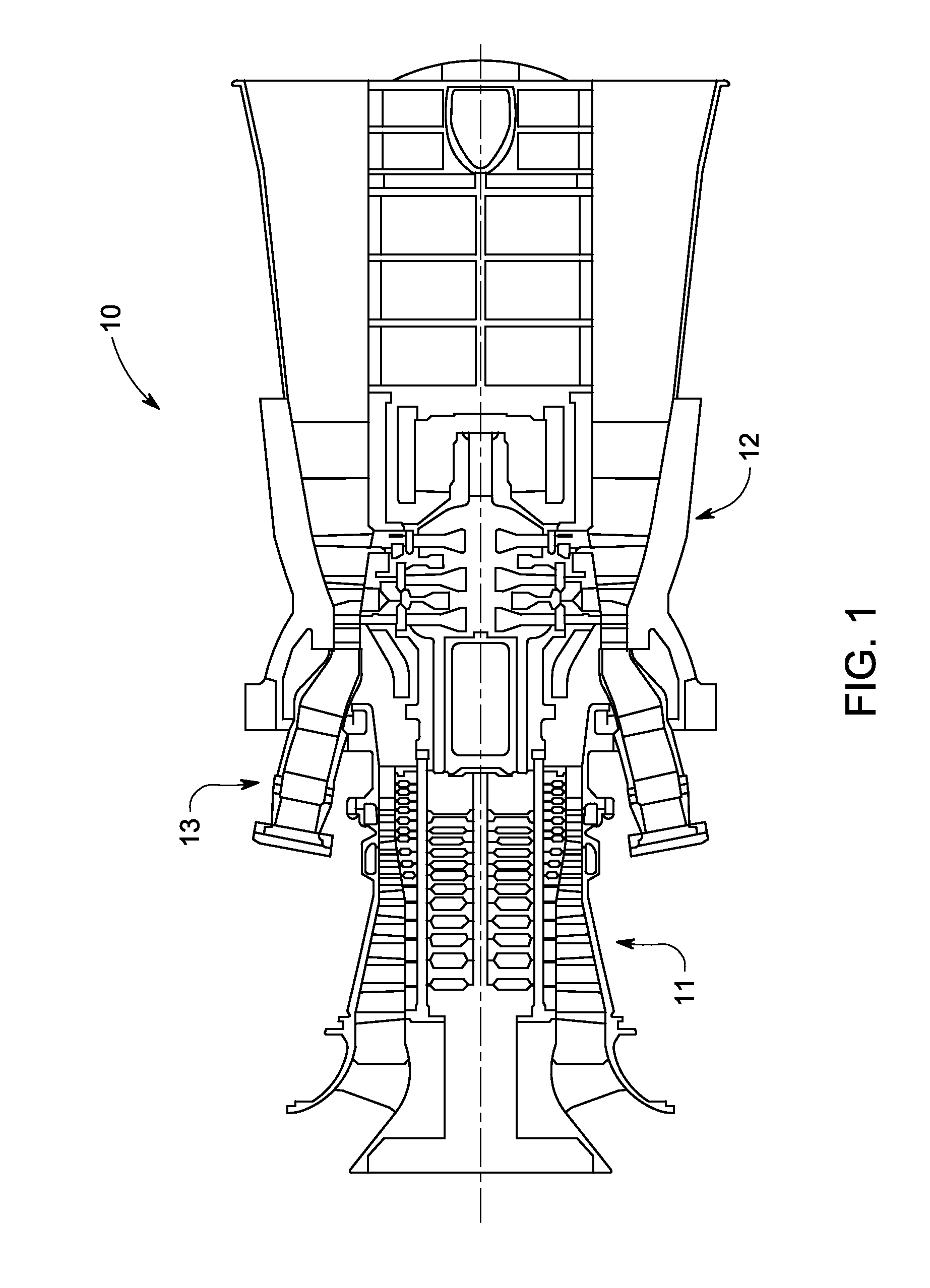
[0019]Referring to FIG. 1, an exemplary embodiment of a turbine system, such as a gas turbine engine 10, is generally illustrated. It will be understood by those skilled in the art that the embodiments described herein are not limited to this type of system. Specifically, in addition to the gas turbine engine 10, other specific embodiments include those gas turbine engines used in airplanes, steam turbine engines, and other type of rotary engines. In general, the gas turbine engine 10 operates by extracting energy from a pressurized flow of hot gas produced by the combustion of a fuel in a stream of compressed air. The gas turbine engine 10 may be configured with a compressor 11 that is mechanically coupled by a common shaft or rotor to a downstream turbine section or a turbine 12, and a combustor 13 positioned between the compressor 11 and the turbine 12.

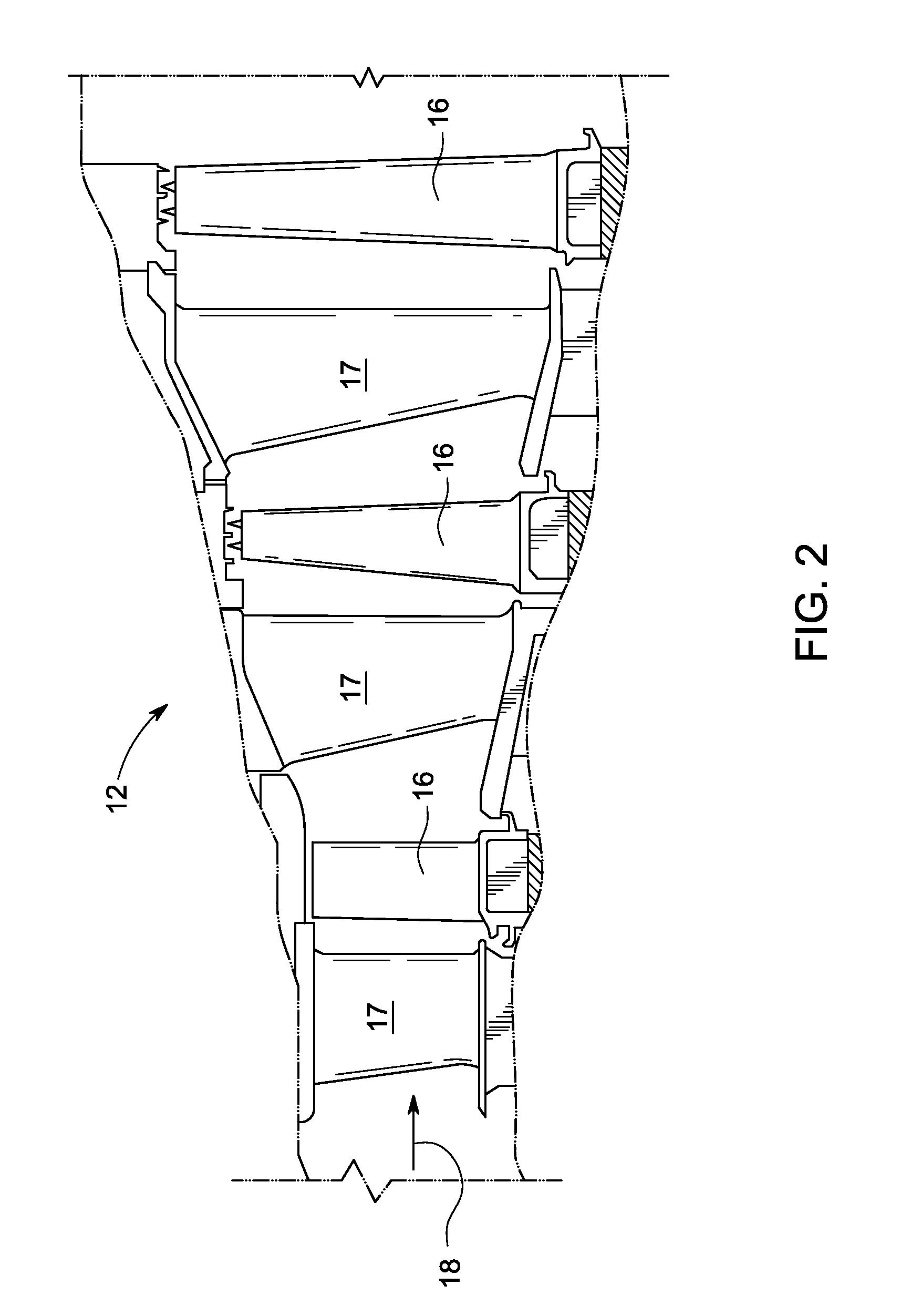
[0020]Referring now to FIG. 2, the turbine 12 that may be used in the gas turbine engine 10 of FIG. 1 is illustrated as a multi-s...


PUM

PropertyMeasurementUnit
Creep rateaaaaaaaaaa
Translucencyaaaaaaaaaa

Abstract

A turbine blade monitoring arrangement includes a bucket tip located at a radial outer location of a bucket. Also included is at least one component disposed radially outwardly of the bucket tip. Further included is a hollow portion of the at least one component, wherein the hollow portion extends radially from a first end to a second end through the at least one component. Yet further included is a first sealing component operatively coupled to the at least one component proximate the first end of the hollow portion, wherein the first sealing component comprises a translucent material. Also included is a proximity sensor disposed radially outwardly of the at least one component and aligned with the hollow portion, the proximity sensor configured to generate a first signal through the hollow portion to the bucket tip.

Description

BACKGROUND OF THE INVENTION[0001]The subject matter disclosed herein relates to turbine systems, and more particularly to a turbine blade monitoring arrangement, as well as a method of manufacturing the turbine blade monitoring arrangement.[0002]Efficiency of a gas turbine engine is impacted by clearance between an outer radial tip of rotor blades and the surrounding stationary structure, which is referred to herein as “tip clearance.” Tighter clearances decrease the leakage flow around the rotor blades, which improves engine efficiency. However, tighter tip clearances increase the risk that rotating parts will make contact with or rub against non-rotating parts during one of the engine's several operational modes, particularly considering that tip clearances generally vary based upon operating conditions. Primarily, this is due to the different thermal expansion characteristics of many of the engine components. Of course, having rotating and stationary parts rub or make contact dur...

Claims


Application Information

Patent Timeline
IPC IPC(8): F01D25/00
CPCF01D25/00F01D17/08F01D11/20Y10T29/49316
Inventor HAFNER, MATTHEW TROY
Owner GENERAL ELECTRIC CO
Why Eureka
Try Eureka