Method of setting a waveform signal in an ultrasound imaging apparatus and apparatus for setting an ultrasonic waveform signal using such method

a technology of ultrasound imaging and waveform signal, which is applied in the field of setting waveform signal in ultrasound imaging apparatus and apparatus for setting ultrasonic waveform signal using such method, can solve the problems of longer time and inability to store data, and achieve the effect of facilitating the setting of different acoustic signal profiles in a dramatically shorter time, facilitating reducing bit rates, and high accuracy of objects

Active Publication Date: 2014-10-30
STMICROELECTRONICS INT NV
View PDF1 Cites 6 Cited by
  • Summary
  • Abstract
  • Description
  • Claims
  • Application Information

AI Technical Summary

Benefits of technology

[0026]It shall be noted that the possibility of having a wide choice in setting different profiles and acoustic signal delays will afford a higher accuracy of the images of the object to be scanned.
[0027]In one embodiment, a method may be provided that facilitates reducing the bit rates, facilitating setting different acoustic signal profiles in a dramatically shorter time than in prior art systems.
[0028]Furthermore, in one embodiment, a negligible increase of circuit complexity may improve bit rate performance and memory savings.

Problems solved by technology

Obviously, storage limited to simple waveforms like the ones of FIG. 4 can be stored, and waveforms like that of FIG. 6A cannot be stored.
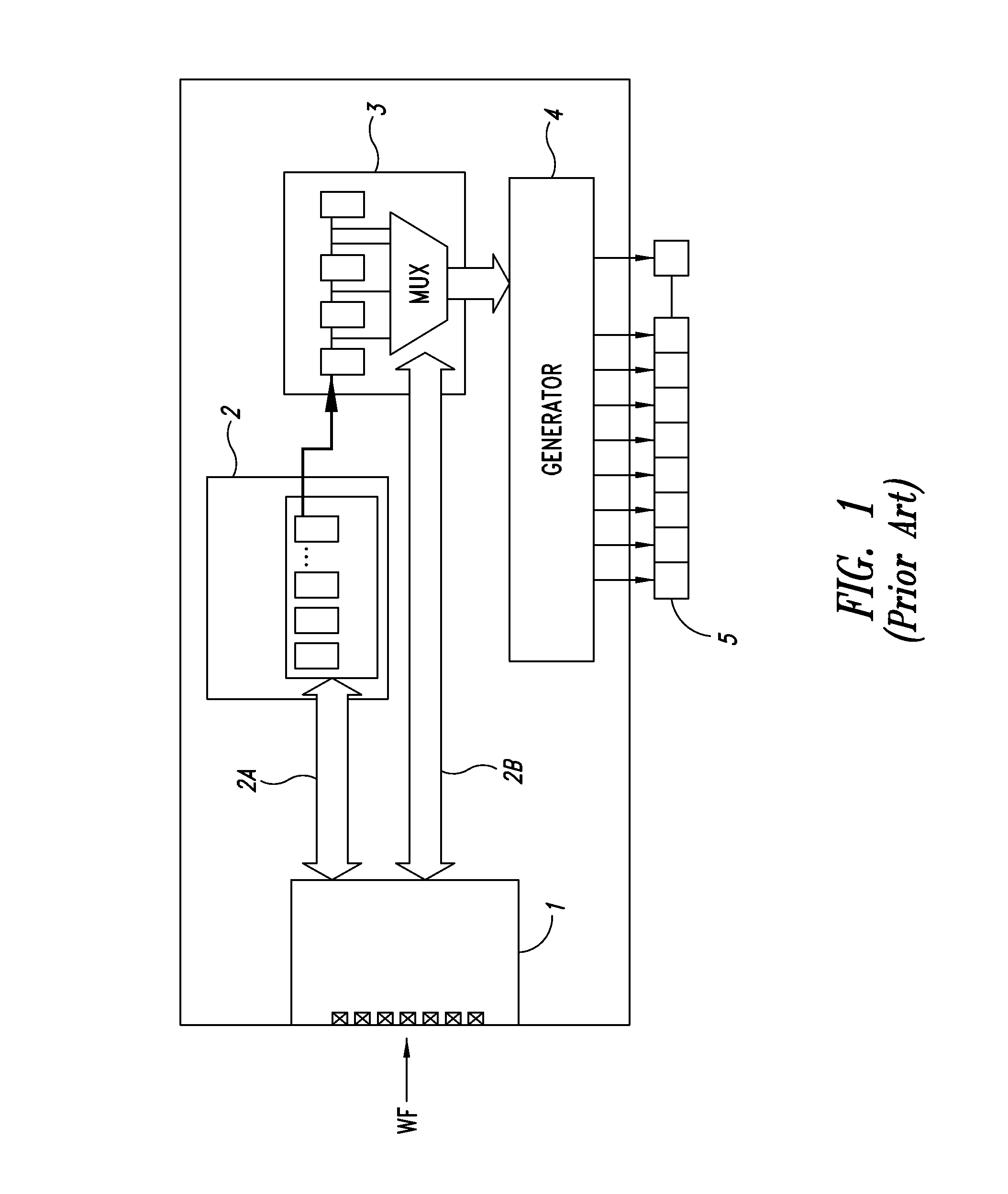
Indeed, as the number of acoustic signal profiles employed for scanning increases, a longer time is needed to configure the system by setting all the descriptive parameters of the different waveforms in use.

Method used


Image

  • Method of setting a waveform signal in an ultrasound imaging apparatus and apparatus for setting an ultrasonic waveform signal using such method
  • Method of setting a waveform signal in an ultrasound imaging apparatus and apparatus for setting an ultrasonic waveform signal using such method
  • Method of setting a waveform signal in an ultrasound imaging apparatus and apparatus for setting an ultrasonic waveform signal using such method

Examples


Embodiment Construction

[0041]In the following description, certain details are set forth in order to provide a thorough understanding of various embodiments of devices, methods and articles. However, one of skill in the art will understand that other embodiments may be practiced without these details. In other instances, well-known structures and methods associated with, for example, signal processing devices, interfaces, etc., have not been shown or described in detail in some figures to avoid unnecessarily obscuring descriptions of the embodiments.

[0042]Unless the context requires otherwise, throughout the specification and claims which follow, the word “comprise” and variations thereof, such as “comprising,” and “comprises,” are to be construed in an open, inclusive sense, that is, as “including, but not limited to.”

[0043]Reference throughout this specification to “one embodiment,”“a first embodiment,”“an embodiment,” etc., means that a particular feature, structure or characteristic described in conne...


PUM


Abstract

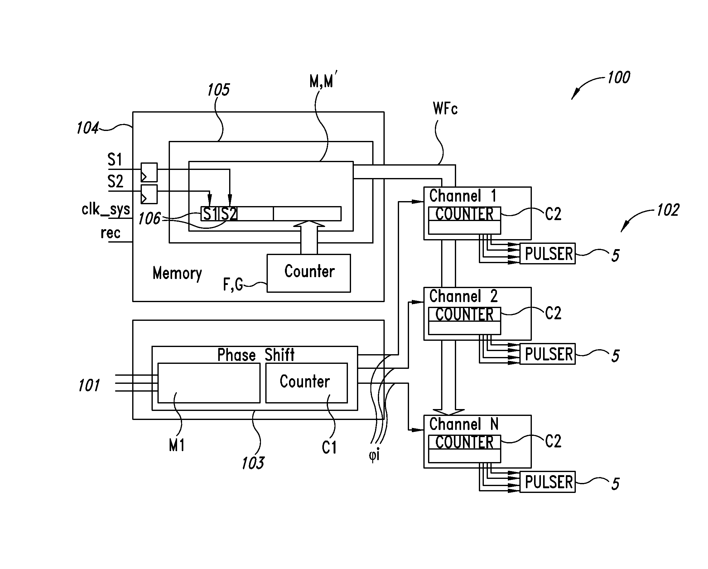
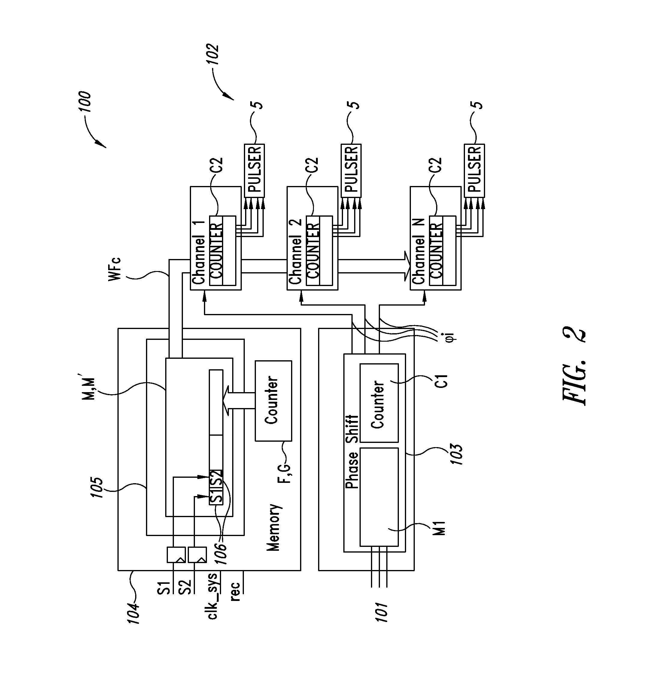
A digital representation of a waveform is generated based on signals received during a recording period. The received signals include a digital clock signal providing a determined number of clock pulses during the recording period, a plurality of binary digital signals defining, for each clock pulse of the determined number of clock pulses, a waveform state associated with the clock pulse. A digital representation of the waveform is generated and storing. The waveform has a duration based on the recording period and a profile based on the defined waveform states associated with the clock pulses of the determined number of clock pulses.

Description

BACKGROUND[0001]1. Technical Field[0002]The present disclosure is directed to a method of setting a waveform signal in an apparatus for ultrasound applications and an apparatus for generating ultrasounds using such method.[0003]The present disclosure is directed to a method and a device that are configured to generate an ultrasonic waveform signal (hereinafter briefly referred to as acoustic signal) for use in an apparatus for ultrasound applications.[0004]2. Description of the Related Art[0005]An apparatus for ultrasound applications is, for instance, an ultrasound or sonographic machine that may comprise a medical diagnostic testing system that uses ultrasonic waves or ultrasounds and is based on the principle of ultrasound transmission and echo emission analysis. Such apparatuses are widely used in internal medicine, surgery and radiology.[0006]In such machine, the acoustic signal is directed to a target region, for example, in the human body, for 2D or 3D scanning, and when the ...

Claims


Application Information

Patent Timeline
Patent Type & Authority Applications(United States)
IPC IPC(8): A61B8/08A61B8/00
CPCA61B8/5292A61B8/5207A61B8/54A61B8/4494G01S7/5202
Inventor BARDELLI, ROBERTO GIORGIOPASSI, STEFANO
Owner STMICROELECTRONICS INT NV
Why Eureka
Try Eureka