Engine health monitoring

a gas turbine engine and engine health technology, applied in the direction of machines/engines, efficient propulsion technologies, instruments, etc., can solve the problems of compromising the design of the aircraft, affecting the performance of the engine, and the bulky structure of the conventional harness itself, so as to reduce the amount of vibration, prolong the life of the raft, and reduce the effect of weigh

Active Publication Date: 2014-11-06
ROLLS ROYCE PLC
View PDF12 Cites 16 Cited by
  • Summary
  • Abstract
  • Description
  • Claims
  • Application Information

AI Technical Summary

Benefits of technology

[0065]Using an anti-vibration mount to attach a raft to a gas turbine engine for example may reduce (or substantially eliminate) the amount (for example the amplitude and/or the number/range of frequencies) of vibration being passed to the raft from the gas turbine engine, for example during use. This may help to prolong the life of the raft. Furthermore, any other components that may be attached to the raft (as discussed above and elsewhere herein) may also benefit from being mounted to the gas turbine engine via the anti-vibration mounts, through being mounted on the raft. For example, the reduced vibration may help to preserve the electrical contact between an electrical raft and any electrical unit connected thereto. As such, any components (such as an electrical unit mounted to the electrical raft) that would conventionally be mounted directly to the gas turbine engine and require at least a degree of vibration isolation no longer require their own dedicated anti-vibration

Problems solved by technology

This makes the conventional harness itself bulky, heavy and difficult to manipulate.
The conventional harnesses occupy significant space within a gas turbine engine (for example within the nacelle of a gas turbine engine), and thus may compromise the design of the aircraft, for example the size and/or weight and/or shape of the nacelle.
This can make the assembly process complicated (and thus susceptible to errors) and/or time consuming.
Disassembly of the conventional harnesses (for example removal of the conventional harnesses from a gas turbine engine during maintenance) may also be complicated and/or time consuming.
Thus, in many maintenance (or repair or overhaul) procedures on a gas turbine engine, removal and subsequent refitting of the conventional electrical harness may account for a very significant portion of the operation time and/or account for a significant proportion of the potential assembly errors.
The electrical conductors in the conventional harnesses may be susceptible to mechanical damage.
For example, mechanical damage may occur during installation (for example through accidental piercing of the protective sleeves/braiding) and/or during service (for example due to vibration).
In order to reduce the likelihood of damage to the conductors in a conventional harness, the protective sleeves/braiding may need to be further reinforced, adding still further weight and reducing the ease with which they can be manipulated.
Similarly, the exposed electrical connectors used to c

Method used


Image

  • Engine health monitoring
  • Engine health monitoring
  • Engine health monitoring

Examples


Embodiment Construction

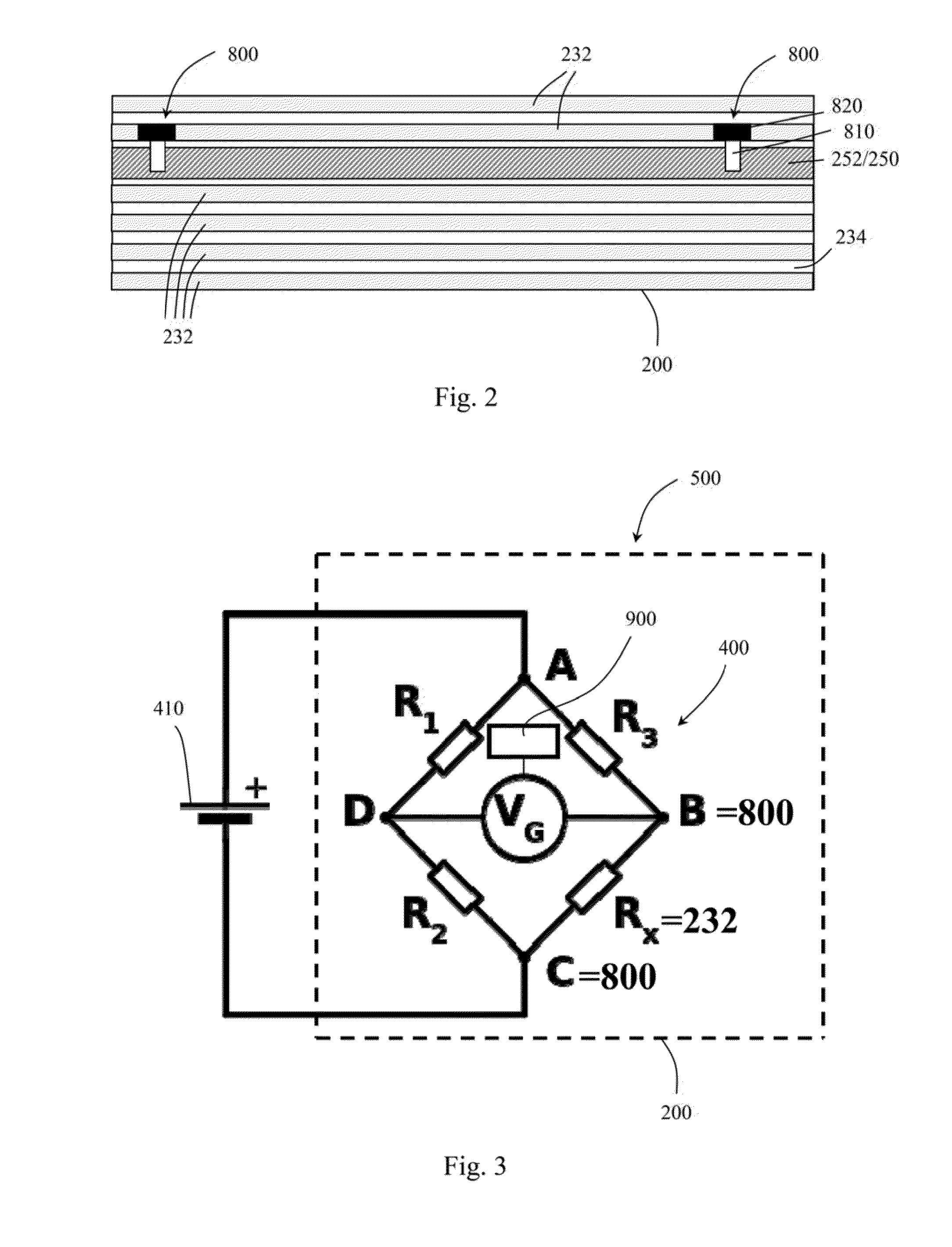
[0076]FIG. 2 shows a schematic cross section of a composite structure 200 according to the present invention. The composite structure 200 may carry at least a part of one or more systems of a vehicle (i.e. vehicle dressings), such as a fluid or electrical system of a gas turbine engine 10, and thus may be referred to as a rigid dressing raft 200.

[0077]The rigid dressing raft 200 in the example of FIG. 2 comprises a plurality of fibre elements 232 reinforcing a polymer base material 234. In FIG. 2, the fibre elements labelled 232 may represent single fibres or bundles of multiple fibres. At least some of the fibres 232 are electrically conductive, and non-metallic, such as carbon fibres.

[0078]The rigid dressing raft 200 in the FIG. 2 example has at least one electrical conductor 252 embedded therein. The electrical conductor 252 may be a part of an electrical system. For example, the rigid dressing raft 200 may be for use with a gas turbine engine 10, and the electrical conductor 252...


PUM


Abstract

A vehicle is provided that has a rigid dressing raft 200. The rigid dressing raft 200 provides a part of a fluid and/or electrical system to the vehicle. The rigid dressing raft comprises elongate fibres 232, which may provide strength to the raft. The fibres 232 are electrically conductive, and a voltage source may be applied to at least one of the fibres. The fibre 232 may form a part of an electrical measurement circuit 400, such as a wheatstone bridge, which may be used to determine the electrical resistance of the fibre 232. The electrical resistance of the fibre 232 may then be used to determine the temperature to and/or stress/strain of the raft 200.

Description

CROSS-REFERENCE TO RELATED APPLICATIONS[0001]This application is based upon and claims the benefit of priority from British Patent Application Number 1308034.6 filed 3 May 2013, the entire contents of which are incorporated by referenceBACKGROUND OF THE INVENTION[0002]1. Field of the Disclosure[0003]The invention relates to an assembly for monitoring parameters of a gas turbine engine, in particular using the resistance of a carbon fibre raft mounted to the engine.[0004]2. Description of the Related Art[0005]A typical gas turbine engine has a substantial number of electrical components which serve, for example, to sense operating parameters of the engine and / or to control actuators which operate devices in the engine. Such devices may, for example, control fuel flow, variable vanes and air bleed valves. The actuators may themselves be electrically powered, although some may be pneumatically or hydraulically powered, but controlled by electrical signals.[0006]Electrical power, and si...

Claims


Application Information

Patent Timeline
IPC IPC(8): G01M15/14G01R27/02
CPCG01M15/14G01R27/02F05D2270/808F01D21/003F02C7/32Y02T50/60
Inventor BROUGHTON, PAUL
Owner ROLLS ROYCE PLC
Why Eureka
Try Eureka