Tabletop Cooking Assembly

a technology for cooking and tabletops, applied in the direction of domestic stoves or ranges, heating types, separation processes, etc., can solve the problems of insufficient capture of the smoke generated on the cooking surface, insufficient heat generation, and melted control panels b>40/b>, etc., to achieve better temperature control and energy efficiency.

Active Publication Date: 2014-11-06
EVO AMERICA LLC
View PDF5 Cites 21 Cited by
  • Summary
  • Abstract
  • Description
  • Claims
  • Application Information

AI Technical Summary

Benefits of technology

[0012]The subject invention provides numerous advantages over the related art assemblies. First, the subject invention ensures complete, or nearly complete, capture of smoked generated on the cooking surface while cooking because the first exhaust duct is not substantially obstructed. Second, the subject invention has better temperature control and energy efficiency because the heating mechanism is insulated and has a larger contact area between the heating elements and the cooking surface.

Problems solved by technology

One drawback to such a configuration is that the assembly has inefficiencies that lead to insufficient capture of the smoke generated on the cooking surface.
Another draw back is that if a fire were to erupt in the exhaust duct 32 adjacent to the control panel 40, a tremendous amount of heat would be generated and result in the control panel 40 being melted, burned, or shorted out, such that any safety mechanisms could not be activated.
These exposed connections 48 generate heat which can result in injury when the teppanyaki assemblies are utilized.
During operation, the retaining plate 50 absorbs the heat from the heating strips 46 and becomes very hot, which exposes users to potential injury.

Method used


Image

  • Tabletop Cooking Assembly
  • Tabletop Cooking Assembly
  • Tabletop Cooking Assembly

Examples


Embodiment Construction

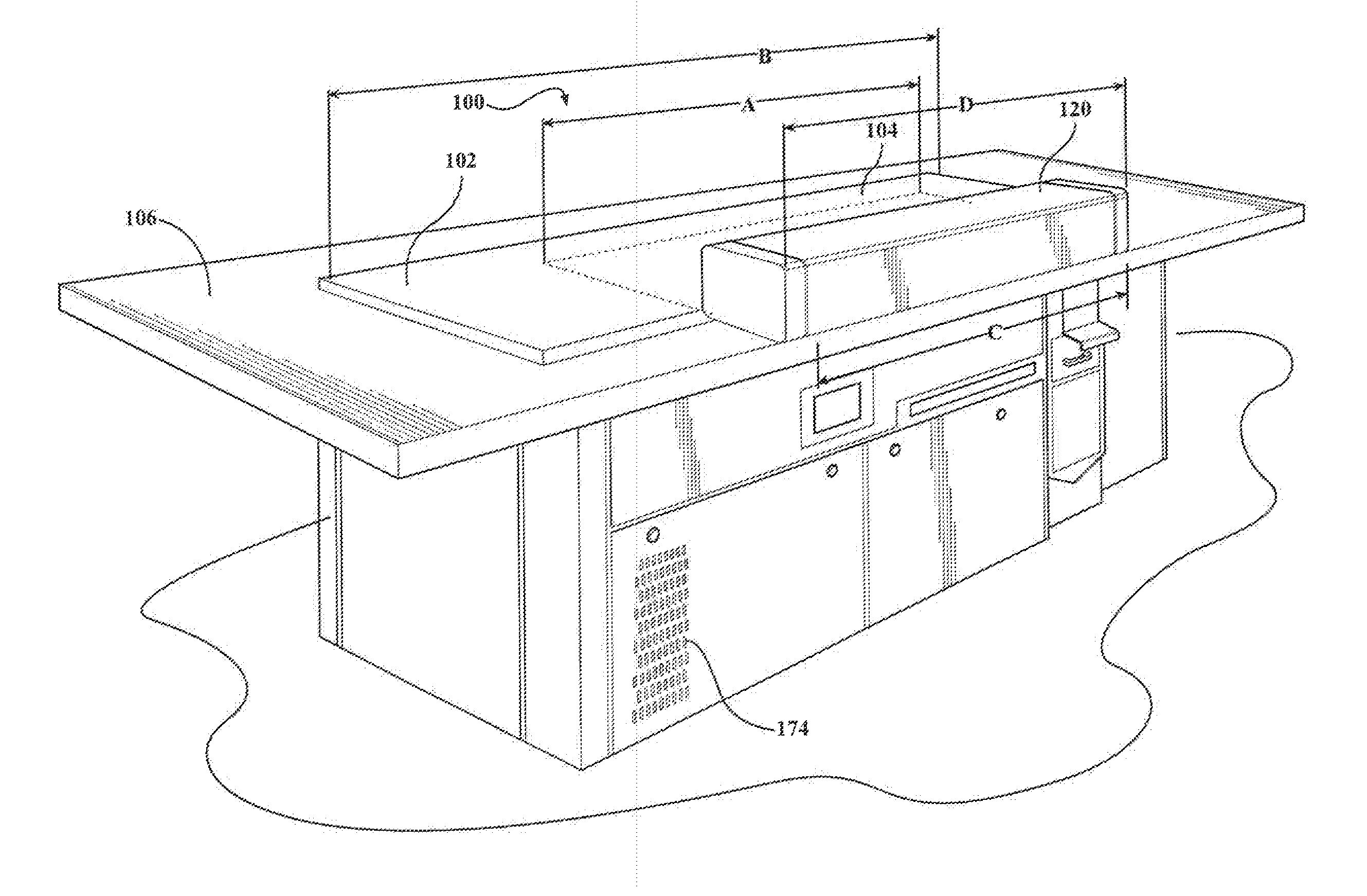
[0031]Referring to the Figures, wherein like numerals indicate like or corresponding parts throughout the several views, a tabletop cooking assembly for preparing foods thereon is shown from a food preparation side generally at 100 in FIG. 3. The food preparation side is to be understood as the side where a chef may be located while preparing food on the assembly 100. The side opposite the preparation side is to be understood as the customer side. The assembly 100 generally comprises a cooking element 102 having a cooking area 104 on a topside for receiving items to be cooked and a serving area 106 adjacent the cooking area 104. The serving area 106 may be configured to seat numerous diners and may be various different shapes, such as square, rectangle, semi-circular, or the like. Similarly, the cooking element 102 may be various shapes depending on the particular configuration. The cooking element 102 may be square, rectangular, semi-circular or the like without deviating from the ...


PUM

PropertyMeasurementUnit
discharge efficiencyaaaaaaaaaa
heightaaaaaaaaaa
discharge efficiencyaaaaaaaaaa

Abstract

A tabletop cooking assembly for preparing foods thereon comprises a cooking element having a cooking area and a vent disposed peripherally to one side of the cooking element defining an aperture for receiving smoke from the cooking element. The assembly includes a first exhaust duct, a filter assembly, an electrostatic precipitator, and a high velocity blower. The first exhaust duct is substantially unobstructed and in fluid communication with the vent for directing smoke away from the cooking element. The high velocity blower is in fluid communication with the first exhaust duct and the filter assembly for drawing smoke from the cooking element through the vent. The heating system includes a retaining plate, a plurality of heating strips, and an insulating material. The heating strips are disposed between the retaining plate and the heating surface to heat the cooking area for preparing foods thereon.

Description

CROSS REFERENCE TO RELATED APPLICATION[0001]This application claims the benefit of U.S. Provisional Patent Application Ser. No. 61 / 818,655 filed May 2, 2013.BACKGROUND OF THE INVENTION[0002]1. Field of the Invention[0003]The present invention relates to a tabletop cooking assembly, particularly to a teppanyaki assembly that has increased cooking efficiently, increased collection of smoke and oil from a cooking surface during operation, and increased safety features.[0004]2. Description of the Related Art[0005]A typical teppanyaki assembly 20, shown in FIG. 1, includes a table frame 22 having a cooking element 24 disposed thereon, a vent 26 defining an aperture 28 and a vent hood 30 disposed adjacent the aperture 28. An exhaust duct 32 is connected to the aperture 28 for directing smoke away from the cooking element 24. The assembly also includes a filter 34 in fluid communication with the vent 26 and in the path of the air flow of the exhaust duct 32 and an electrostatic precipitato...

Claims


Application Information

Patent Timeline
Patent Type & Authority Applications(United States)
IPC IPC(8): A47J37/06A47J27/62F24C15/20
CPCA47J37/0676A47J27/62F24C15/2035F24C15/2042B01D46/0032B01D46/0095B01D46/4236B01D46/446B01D46/46
Inventor MCEVOY, WILLIAM B.
Owner EVO AMERICA LLC
Why Eureka
Try Eureka