Unlock instant, AI-driven research and patent intelligence for your innovation.
Supercharged internal combustion engine
Inactive Publication Date: 2014-11-06
TOYOTA JIDOSHA KK
View PDF0 Cites 21 Cited by
Summary
Abstract
Description
Claims
Application Information
AI Technical Summary
This helps you quickly interpret patents by identifying the three key elements:
Problems solved by technology
Method used
Benefits of technology
Benefits of technology
The present invention aims to provide a supercharged internal combustion engine that can prevent the buildup of a deposit in the compressor.
Problems solved by technology
However, a situation is conceivable where introduction of blow-by gas into the air intake passage through the communication passage is not performed when some sort of control is performed.
Method used
Image
Click on the blue label to locate the original text in one second.
Reading with bidirectional positioning of images and text.
Examples
embodiment 1
Control Specific to Embodiment 1
[0173]The inventors of the present invention eagerly studied and found that when oil is brought into the internal passage in the compressor 18b in such a large amount that any part of the oil can not stay long enough to be able to evaporate, no deposit is generated and a significant effect of scaling and removing a deposit attached to the compressor 18b can be obtained.
[0174]In the present embodiment, the amount of oil to be supplied into the internal passage in the compressor 18b is increased when a deposit buildup operation condition is met such that there is a concern of a buildup of a deposit in the compressor 18b due to oil contained in blow-by gas is increased compared with when the deposit buildup operation condition is not met.
[0175]More specifically, if a deposit builds up in the compressor 18b, the compressor efficiency is reduced. In the present embodiment, when the compressor efficiency is reduced to a value equal to or smaller than a pred...
embodiment 2
[0209]Embodiment 2 of the present invention will be described with reference mainly to FIGS. 15 and 16.
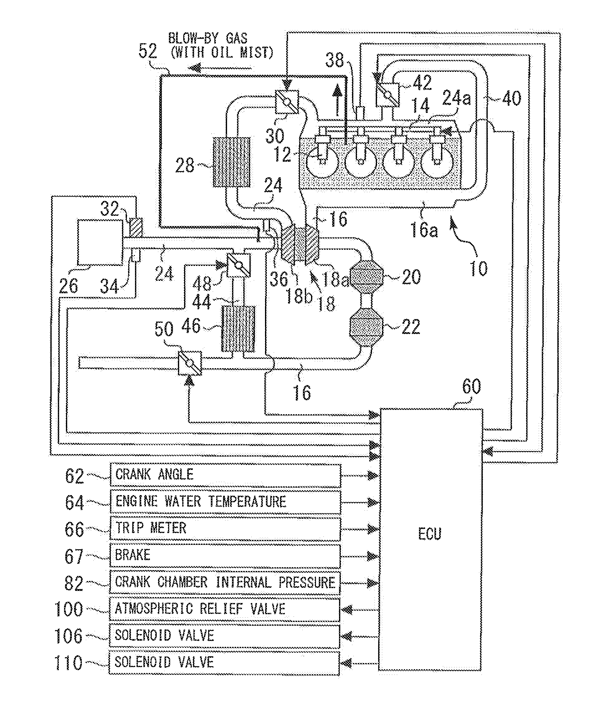
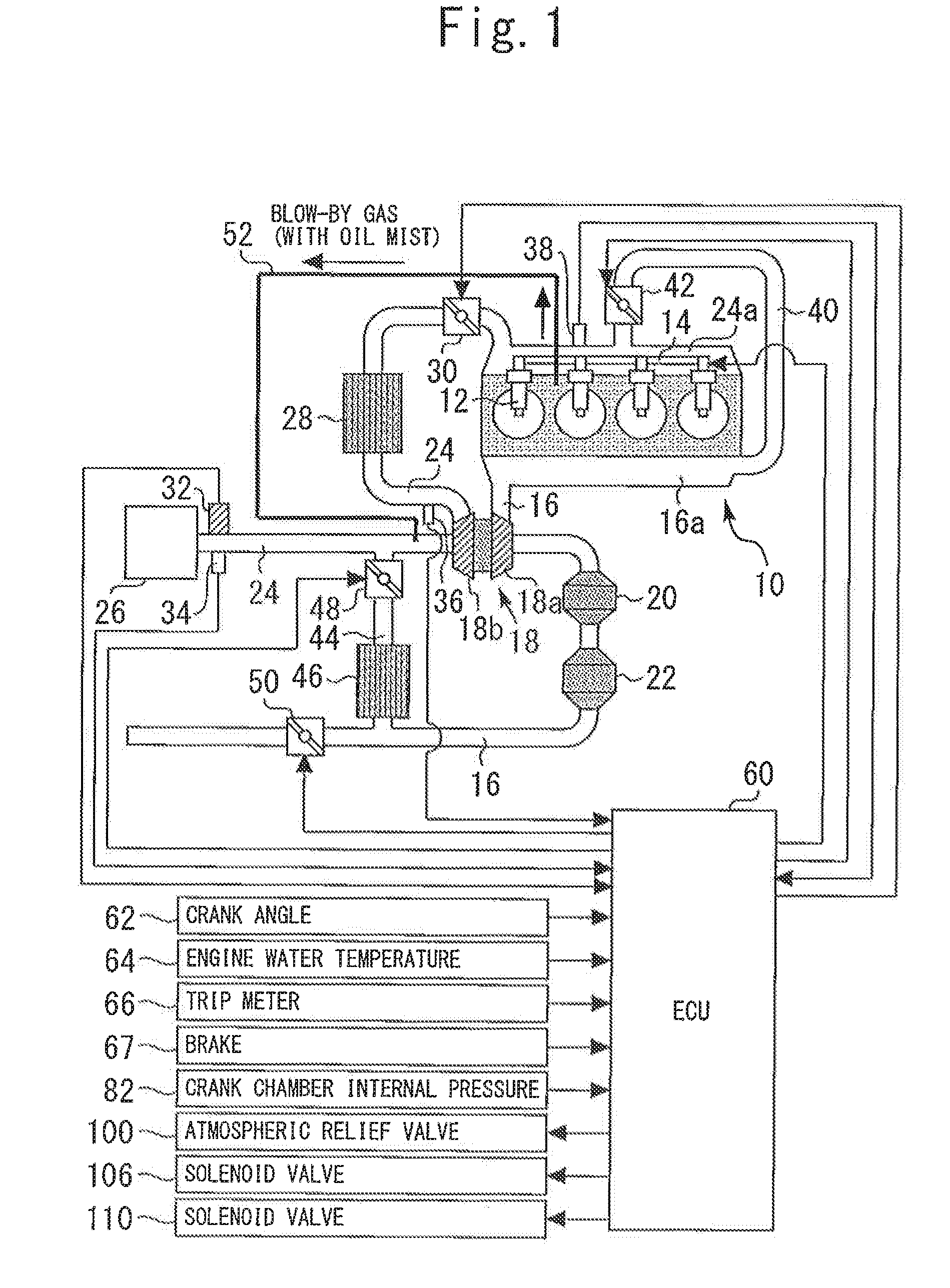
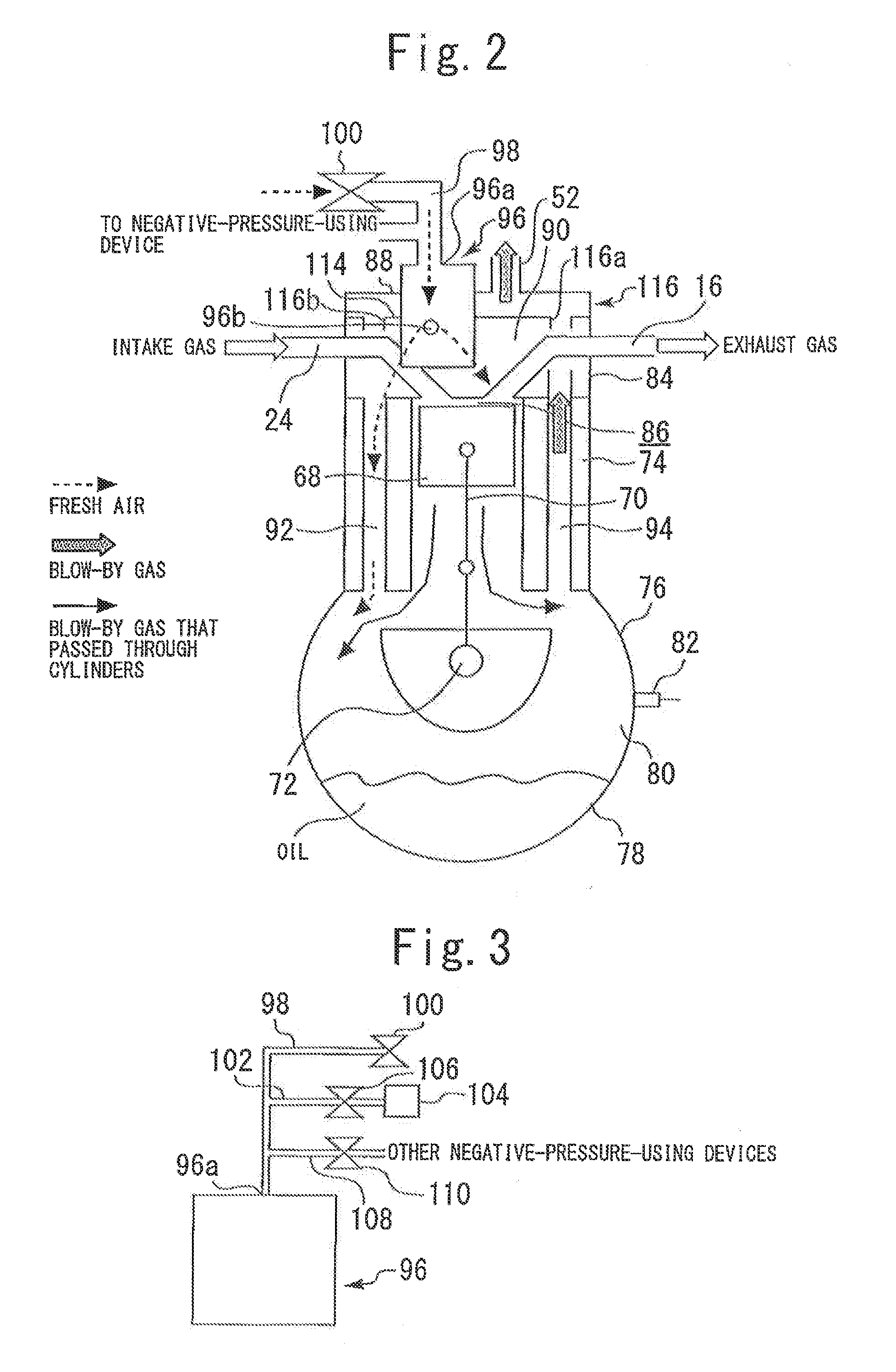
[0210]The system in the present embodiment can be implemented by using the hardware arrangement shown in FIGS. 1 to 6 and by making the ECU 60 execute a routine described later with reference to FIG. 15 in place of the routine shown in FIG. 9.
[0211]In Embodiment 1 described above, if it is determined that the compressor efficiency is reduced to a value equal to or lower than a predetermined value, it is then determined that the deposit buildup operation condition is met. That is, in the system in Embodiment 1, if it is inferred from a reduction in compressor efficiency that a buildup of a deposit has actually occurred, it is then determined that the deposit buildup operation condition is met under which there is a concern of a buildup of a deposit in the compressor 18b. Upon making this determination, the atmospheric relief valve 100 is opened for deposit cleaning (sweeping) (the d...
modified example of embodiment 2
[0222]Embodiment 2 has been described with respect to an example in which the atmospheric relief valve 100 is opened to a predetermined degree of opening when the deposit buildup operation condition is met. However, the atmospheric relief valve 100 may be controlled so as to be intermittently opened as in a routine described below with reference to FIG. 17 when the deposit buildup operation condition is met.
[0223]FIG. 17 is a flowchart showing a control routine executed by the ECU 60 to realize control specific to a modified example of Embodiment 2 of the present invention. In FIG. 17, the same steps as those shown in FIG. 15 for Embodiment 2 are indicated by the same reference characters. The same description of them will not be repeated or abbreviated descriptions will be made of them.
[0224]In the routine shown in FIG. 17, if, after the affirmative result of determination in step 200 as to oil degradation, it is determined in step 204 that the deposit buildup mode is established, ...
PUM
Abstract
A supercharged internal combustion engine of the present invention is provided with a turbocharger (18) having a compressor (18b) in an air intake passage (24), a communication passage (52) connected between an upstream-side portion of the air intake passage (24) on the upstream side of a compressor impeller (18b3) and an internal space (90) of the internal combustion engine (10), and an oil supply apparatus (96, 98, 100) that supplies oil to an internal passage in the compressor (18) through which intake air flows. When a deposit buildup operation condition under which there is a concern of a buildup of a deposit in the compressor (18) is met, the oil supply apparatus (96, 98, 100) increases the amount of oil supplied to the internal passage compared with the amount of oil supplied when the deposit buildup operation condition is not met.
Description
CROSS-REFERENCE TO RELATED APPLICATIONS[0001]This application is a national phase application of International Application No. PCT / JP2012 / 067381, filed Jul. 6, 2012, and claims the priority of International Application No. PCT / JP2011 / 077827, filed Dec. 1, 2011, and Japanese Application No. 2012-030926, filed Feb. 15, 2012, the content of all of which is incorporated herein by reference.TECHNICAL FIELD[0002]The present invention relates to a supercharged internal combustion engine.BACKGROUND ART[0003]A supercharged internal combustion engine such as disclosed in Patent Document 1 is known. This conventional internal combustion engine has a throttle valve disposed in an air intake passage on the downstream side of a compressor, a first communication passage for communication between the air intake passage on the downstream side of the throttle valve and a crank chamber, and a second communication passage for communication between the air intake passage on the upstream side of the comp...
Claims
Application Information
Patent Timeline
Application Date:The date an application was filed.
Publication Date:The date a patent or application was officially published.
First Publication Date:The earliest publication date of a patent with the same application number.
Issue Date:Publication date of the patent grant document.
PCT Entry Date:The Entry date of PCT National Phase.
Estimated Expiry Date:The statutory expiry date of a patent right according to the Patent Law, and it is the longest term of protection that the patent right can achieve without the termination of the patent right due to other reasons(Term extension factor has been taken into account ).
Invalid Date:Actual expiry date is based on effective date or publication date of legal transaction data of invalid patent.
Patent Type & Authority Applications(United States)

