Eureka AIR delivers breakthrough ideas for toughest innovation challenges, trusted by R&D personnel around the world.

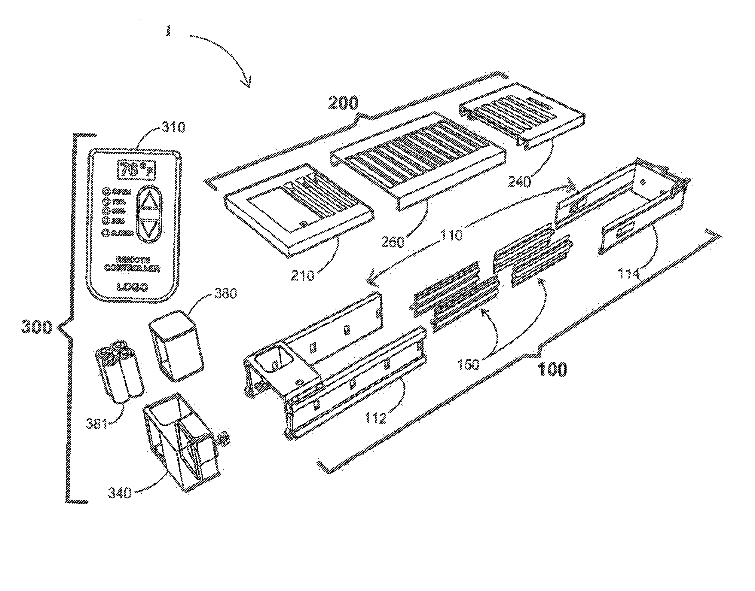
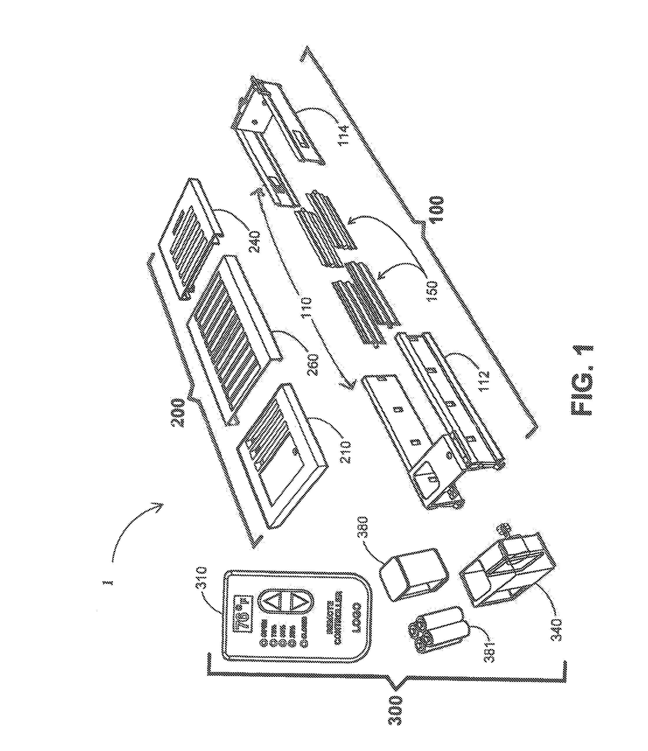
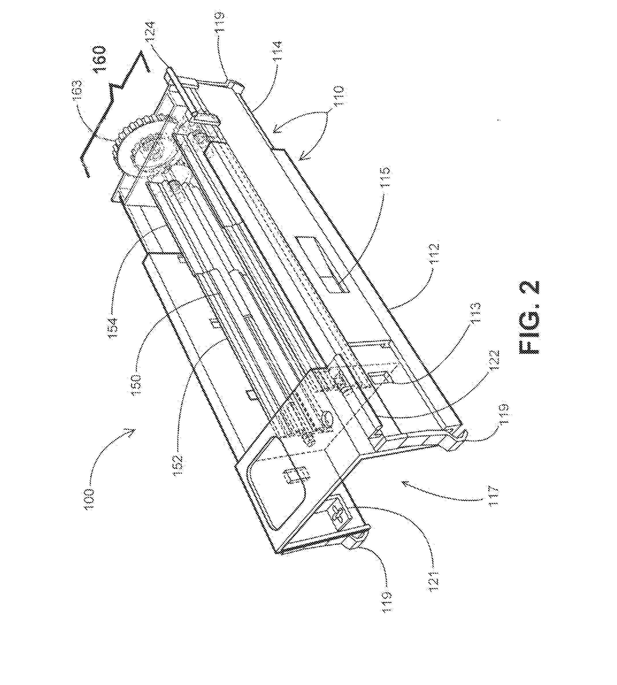
Adjustable register vent and grill assembly designed to fit all size standard air distribution boot openings

a register vent and grill assembly technology, applied in the field of independent air register vent and grill assembly, can solve the problems of inability of the system's main blower to provide an adequate volume of conditioned air, inability of the located thermostat to satisfy the predetermined desired temperature equally throughout the room, and described shortfalls that are not only inconvenient in terms of comfort, but waste energy, resources and money

Inactive Publication Date: 2014-11-06
ADJUSTAVENT
View PDF37 Cites 22 Cited by
  • Summary
  • Abstract
  • Description
  • Claims
  • Application Information

AI Technical Summary

Benefits of technology

The patent describes an adjustable register assembly for regulating airflow through an opening. The assembly includes a register assembly with a lengthwise adjustable register and lengthwise adjustable slats that can be opened or closed to control airflow. The assembly also includes a motor-receiver assembly and a remote transmitter for remotely controlling the motor. The adjustable register assembly can be attached to the opening, and the grill assembly can be positioned for different airflow needs. The system allows for precise control of airflow through the opening.

Problems solved by technology

Typical ventilating configurations have common disadvantages in that they must generate sufficient cool or warm air flowing towards all the rooms whether occupied are not.
Other disadvantages are related to the inability of the system's main blower to provide an adequate volume of conditioned air flowing to each single room throughout the home or structure.
Given the fact that various rooms in a particular structure tend to be unequal in size and volume, this causes a system with a centrally located thermostat incapable of satisfying the predetermined desired temperature equally throughout the rooms in a particular home or structure.
The described shortfalls are not only inconvenient in terms of comfort but waste energy, resources and money.
However, most of the ventilation outlets are typically mounted on the ceiling of the room or a remote part of the floor of the room, not easily accessible to the occupant.
Ceiling mounted air vent registers in most cases present a great deal of inconvenience for the user as they must climb up to the ceiling in order to manually move the lever or gear to regulate the desired air flowing through the register outlet.
The exercise of physically moving the louver control lever is simply too inconvenient, therefore leaving the room environment inefficiently controlled and the occupant dissatisfied.
The cost may be prohibitive to many homeowners.
Herron '962 fails to disclose or suggest non-manual, computer-controlled adjustment settings of louver positions into partially open or partially closed positions, and fails to disclose a length-adjustable vent housing and length-adjustable louvers.
Brinkerhoff '349 fails to disclose or suggest setting the louvers into other than open and closed positions, use of one way transmission (a transmitter and receiver, reducing complexity and cost, rather than paired transceivers) to set louver positions into partially open or partially closed positions, and fails to disclose a length-adjustable vent housing and length-adjustable louvers.
Kates '777 fails to disclose or suggest a length-adjustable vent housing and length-adjustable louvers.
Kates '777 fails to disclose or suggest a length-adjustable grill cover that may be swung open from the vent or removed, providing access to a replaceable filter.
These devices have major drawbacks in that they are typically difficult for the user to program.
Their internal programming and components are complex and come with expense.
Each repeated opening or closing of a vent drains power at the vent, requiring significant power capacity at the vent location.

Method used


Image

  • Adjustable register vent and grill assembly designed to fit all size standard air distribution boot openings
  • Adjustable register vent and grill assembly designed to fit all size standard air distribution boot openings
  • Adjustable register vent and grill assembly designed to fit all size standard air distribution boot openings

Examples


Embodiment Construction

[0057]U.S. Provisional Application No. 61 / 849,662, filed Jan. 30, 2013 for ADJUSTABLE REGISTER VENT AND GRILL ASSEMBLY DESIGNED TO FIT ALL SIZE STANDARD AIR DISTRIBUTION BOOT OPENINGS by Richard D. Frank is herein incorporated by reference in its entirety. U.S. Provisional Ser. No. 14 / 167,783, filed Jan. 29, 2014 for ADJUSTABLE REGISTER VENT AND GRILL ASSEMBLY DESIGNED TO FIT ALL SIZE STANDARD AIR DISTRIBUTION BOOT OPENINGS by Richard D. Frank is herein incorporated by reference in its entirety.

[0058]An object of an example of the present invention is to provide an independent air register vent and grill assembly that improves on the shortcomings of prior art devices. In example, the assembly allows for the means to adjust the register frame and louver components, rotatable and non-rotatable, to match standard length and width openings in a manner that arranges the entire assembly to conform to all common standard size vent boot outlets. In one embodiment, within the main register f...


PUM


Abstract

An apparatus, methods and systems for an independent air register vent assembly having a register frame assembly, louver components, and a means to adjust the register frame assembly and louver components to a range of lengths and / or widths. A length and / or width adjustable grill assembly covers the register frame assembly. A removable motor-receiver is attached to operate the louver components. The motor-receiver places the louvers into open, closed, and one or more intermediate positions. The louvers may also be manually operated. A remote transmitter controls the motor-receiver. An optional digital thermometer on the transmitter passively displays the room temperature. Low battery and re-powering conditions move the louvers into fully open positions. The air register vent assembly is installable in one or more configurations: manual only, with motor-receiver, and / or with remote transmitter, depending on the option selected. The register vent assembly option can be changed in the field.

Description

CROSS REFERENCE TO RELATED APPLICATIONS[0001]This application is a continuation-in-part of, and claims the benefit of, U.S. application Ser. No. 14 / 167,783, filed Jan. 29, 2014, which claims the benefit of U.S. Provisional Application No. 61 / 849,662, filed Jan. 30, 2013.BACKGROUND OF THE INVENTION[0002]1. Field of the Invention[0003]Examples of the subject matter disclosed herein generally relate to apparatus, methods and systems for an independent air register vent and grill assembly that can be easily installed and removed by a homeowner or general handyman, in many cases without the use of tools.[0004]2. Discussion of Background[0005]The present invention relates to the common comfort demands, convenience and expense of over-heated or overcooled rooms whether occupied or unoccupied.[0006]Ventilation systems are common place in all modern structures such as offices or homes providing a comfortable indoor climate controlled condition for the occupants. The occupants are able to tur...

Claims


Application Information

Patent Timeline
Patent Type & Authority Applications(United States)
IPC IPC(8): F24F11/00F24F13/14F24F13/08
CPCF24F11/0012F24F13/084F24F2013/1433F24F11/0076F24F13/1426F24F13/075F24F11/30F24F2110/10F24F11/56F24F11/76F24F11/523F24F11/63
Inventor FRANK, RICHARD D.
Owner ADJUSTAVENT
Why Eureka
Eureka Blog
Learn More