
Network Security and Variable Pulse Wave Form with Continuous Communication

a network security and pulse wave technology, applied in the field of network security and variable pulse wave form with continuous communication, can solve the problems of communication and/or data transfer, difficult choice, and difficult choice for facilities or businesses, and achieve the effect of improving ensuring the security of the network

Active Publication Date: 2014-11-06
FEDERAL LAW ENFORCEMENT DEV SERVICES
View PDF5 Cites 13 Cited by
  • Summary
  • Abstract
  • Description
  • Claims
  • Application Information

AI Technical Summary

Benefits of technology

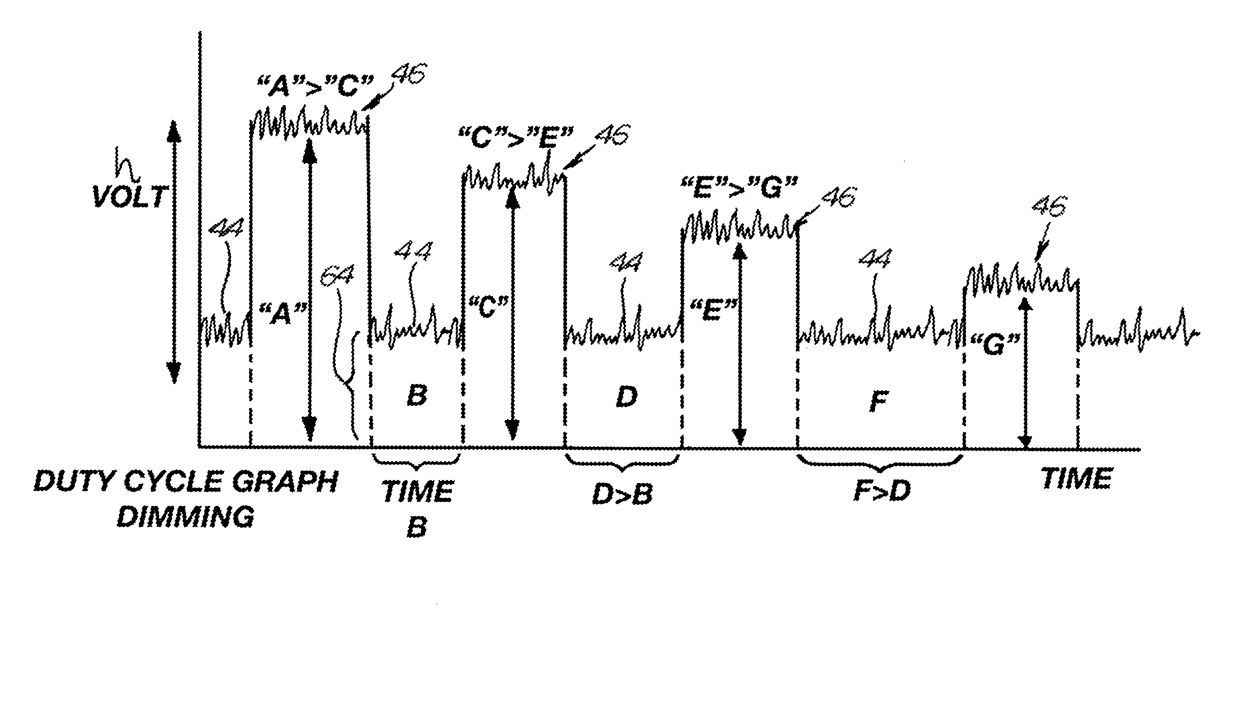
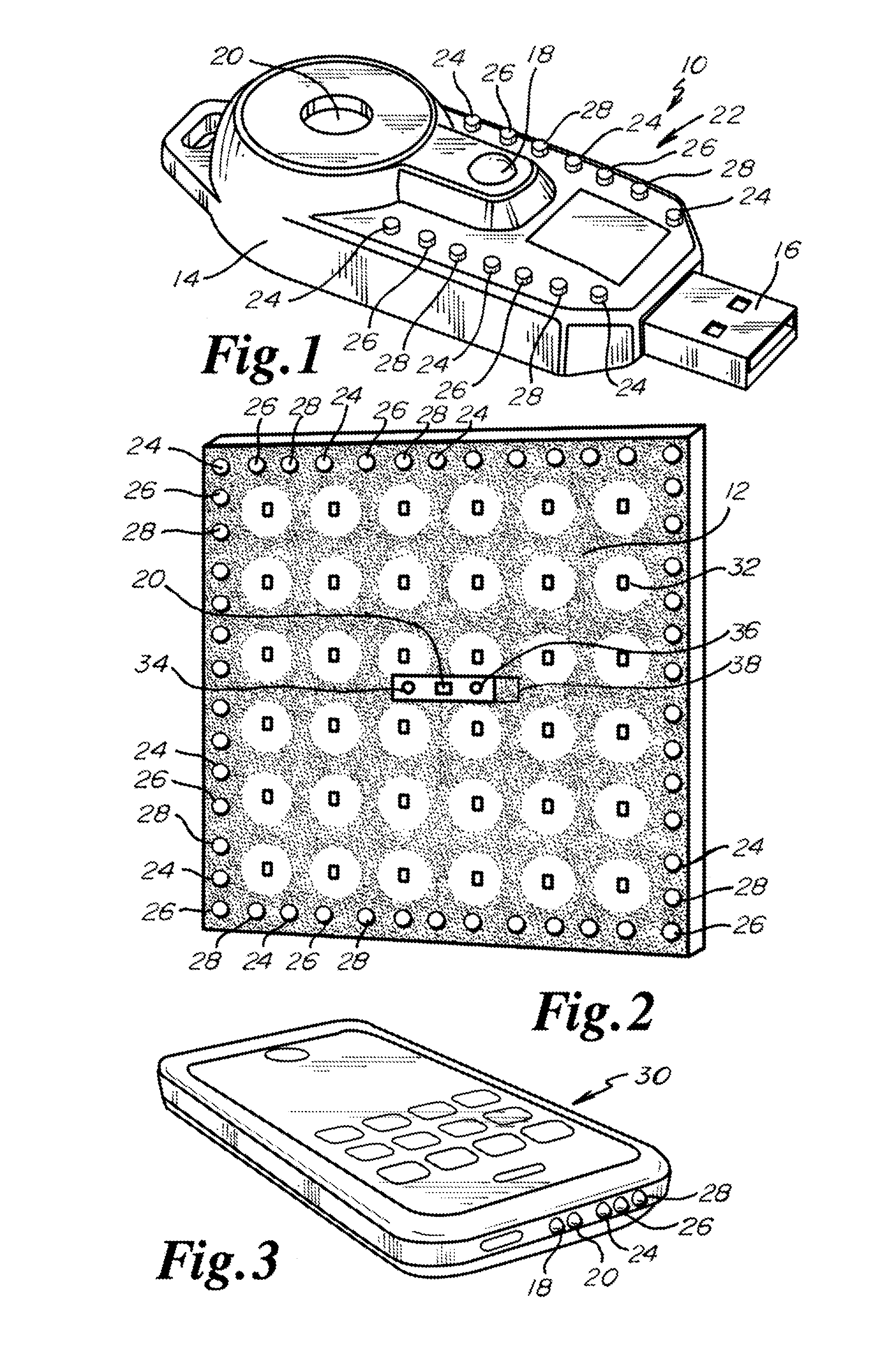
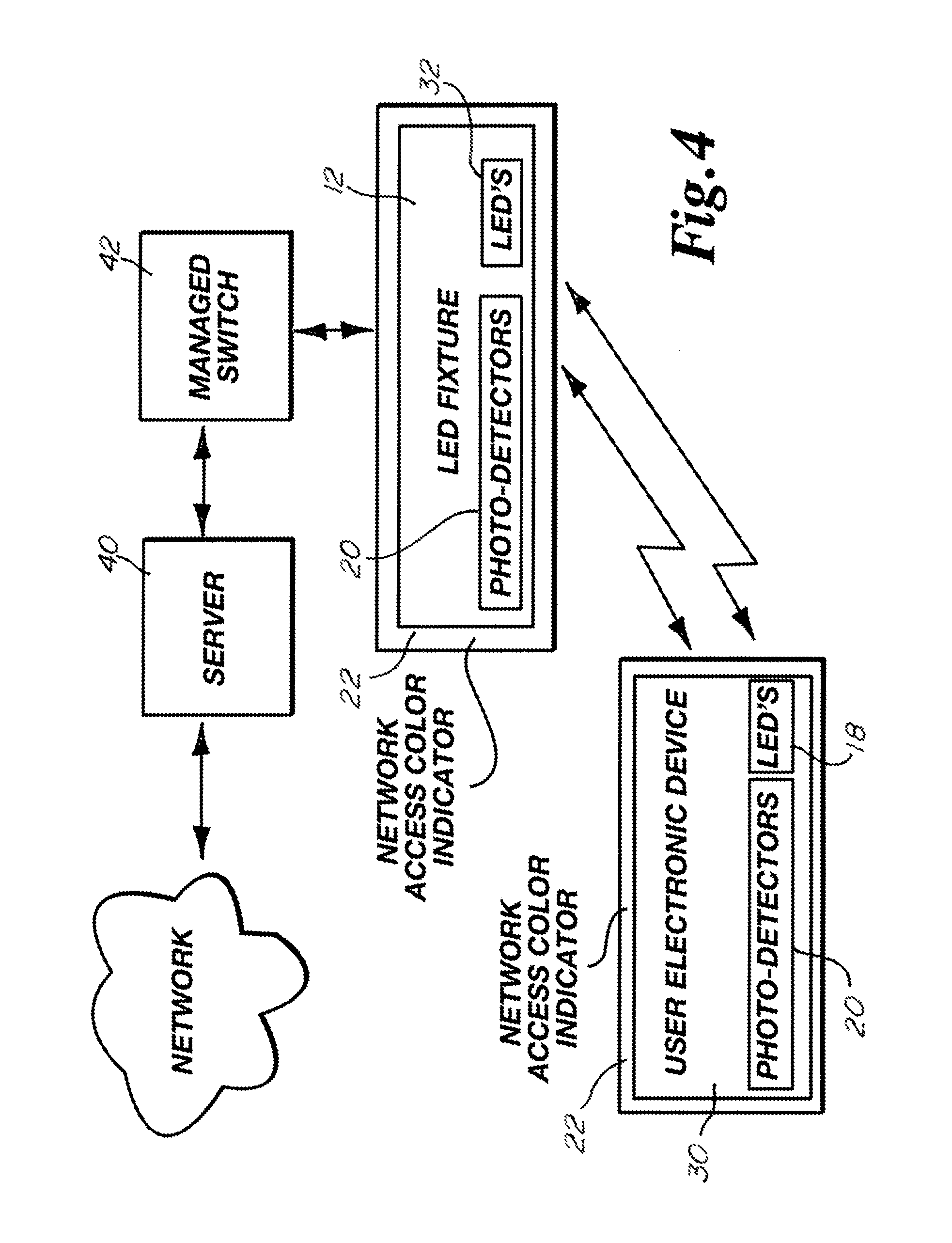
The invention is a pulsed light communication device that includes a controller, transmission light emitting diode, photo detector, indicator light emitting diodes, and a network interface. The device can communicate with a network and illuminate the indicator light emitting diodes to emit colored light to identify the network security level. The device can also generate a continuous uninterrupted modulated pulsed light emitting diode light signal with a sensitivity threshold detection level to transmit information or data. The information or data can include global positioning system information. The technical effects of the invention include improved network security and the ability to transmit information or data using a pulsed light communication device.

Problems solved by technology

In the past Wi-Fi Internet security within a building has been problematic, especially within public areas.
A facility or business has been faced with many difficult choices particularly when accommodating customer or employee convenience and security concerns related to networks, secure information and / or data as stored on servers.
In the past, communication and / or data transfer as embedded within pulsed light emitting diode (LED) light transmissions, and reception of pulsed LED light carrier signals has not been optimized when LED lights have been modulated through a power off state during a transmission cycle.
The known modulation techniques actuate the LED's between an on transmission status through an off non-transmission status which in turn causes the memory or the memory cache for the information or data transmission to become exhausted or saturated, slowing the communication rate for the transmission of information and / or data embedded within the pulsed LED light carrier signals.

Method used


Image

  • Network Security and Variable Pulse Wave Form with Continuous Communication
  • Network Security and Variable Pulse Wave Form with Continuous Communication
  • Network Security and Variable Pulse Wave Form with Continuous Communication

Examples


first embodiment

[0105]In a first embodiment a security system is disclosed comprising: a pulsed light communication device comprising at least one transmission light emitting diode, at least one photo detector, and a plurality of indicator light emitting diodes, said plurality of indicator light emitting diodes emitting at least one of a plurality of wavelengths of colored light; and a controller in communication with said at least one transmission light emitting diode, said at least one photo detector, and said plurality of indicator light emitting diodes; wherein said pulsed light communication device is in communication with at least one network, said at least one network having a network security level, said network security level being identified by at least one of said plurality of wavelengths of colored light; wherein said controller is constructed and arranged to communicate with said network and to illuminate said indicator light emitting diodes to emit said at least one wavelength of colo...

tenth embodiment

[0114]In a tenth embodiment a security system is disclosed comprising an electronic device, said electronic device being in communication with a pulsed light communication device, said electronic device comprising a controller, at least one transmission light emitting diode, at least one photo detector, a network interface and a plurality of indicator light emitting diodes, said plurality of indicator light emitting diodes comprising light emitting diodes emitting at least one of a plurality of wavelengths of colored light, said controller being in communication with said at least one transmission light emitting diode, said at least one photo detector, and said plurality of indicator light emitting diodes, said electronic device being in communication with at least one network, said at least one network having a network security level, said network security level being identified by at least one of said plurality of wavelengths of colored light, said controller being constructed and...

eleventh embodiment

[0115]In an eleventh embodiment according to the tenth embodiment comprising a second pulsed light communication device comprising at least one second transmission light emitting diode, at least one second photo detector, and a plurality of second indicator light emitting diodes, said plurality of second indicator light emitting diodes emitting at least one of a plurality of wavelengths of colored light and a second controller in communication with said at least one second transmission light emitting diodes, said at least one second photo detector, and said plurality of second indicator light emitting diodes wherein said pulsed light communication device is in communication with said at least one network, said second controller being constructed and arranged to communicate with said network and to illuminate said second indicator light emitting diodes to emit said at least one wavelength of colored light identified for said network security level.

[0116]In a twelfth embodiment the pu...


PUM


Abstract

A pulsed light communication device has a plurality of indicator light emitting diodes emitting diodes emitting at least one of a plurality of wavelengths of colored light to correspond to a designated color assigned to a security level for a network. A continuous uninterrupted modulated pulsed light emitting diode light signal may be generated having a sensitivity threshold detection level exceeding minimal parameters of a photodetector.

Description

CROSS-REFERENCE TO RELATED APPLICATIONS[0001]This application claims the benefit of U.S. Provisional Patent Application Ser. No. 61 / 819,861, which was filed May 6, 2013, which is incorporated herein by reference in its entirety.BACKGROUND OF THE INVENTION[0002]In the past Wi-Fi Internet security within a building has been problematic, especially within public areas. A facility or business has been faced with many difficult choices particularly when accommodating customer or employee convenience and security concerns related to networks, secure information and / or data as stored on servers. Frequently a company or facility has needed to balance individual needs to access a Wi-Fi networks or servers and security to confidential and / or proprietary information. The present invention provides a unique and convenient method to improve security within a facility with respect to a number of types of networks and Internet access within public, semi-private and / or private areas.[0003]In the pa...

Claims


Application Information

Patent Timeline
IPC IPC(8): H04B10/116
CPCH04B10/116H04B10/502H04B10/40H04B10/524
Inventor PEDERSON, JOHN C.VOGT, TIMOTHY J.
Owner FEDERAL LAW ENFORCEMENT DEV SERVICES
Learn More