Vibration isolation mount

Active Publication Date: 2014-11-06
DYSON TECH LTD
View PDF8 Cites 35 Cited by
  • Summary
  • Abstract
  • Description
  • Claims
  • Application Information

AI Technical Summary

Benefits of technology

[0011]The compressor may comprise a centrifugal impeller located downstream of the axial inlet and upstream of the radial outlet. By employing a radial outlet, the fluid exit

Problems solved by technology

In contrast, if o-rings were employed, the friction generated between the o-rings and the housing would make it difficult to insert the compressor into the recess.
Although the lip seal contacts the housing over a relatively large area, the lip seal is intended only t

Method used


Image

  • Vibration isolation mount
  • Vibration isolation mount
  • Vibration isolation mount

Examples


Embodiment Construction

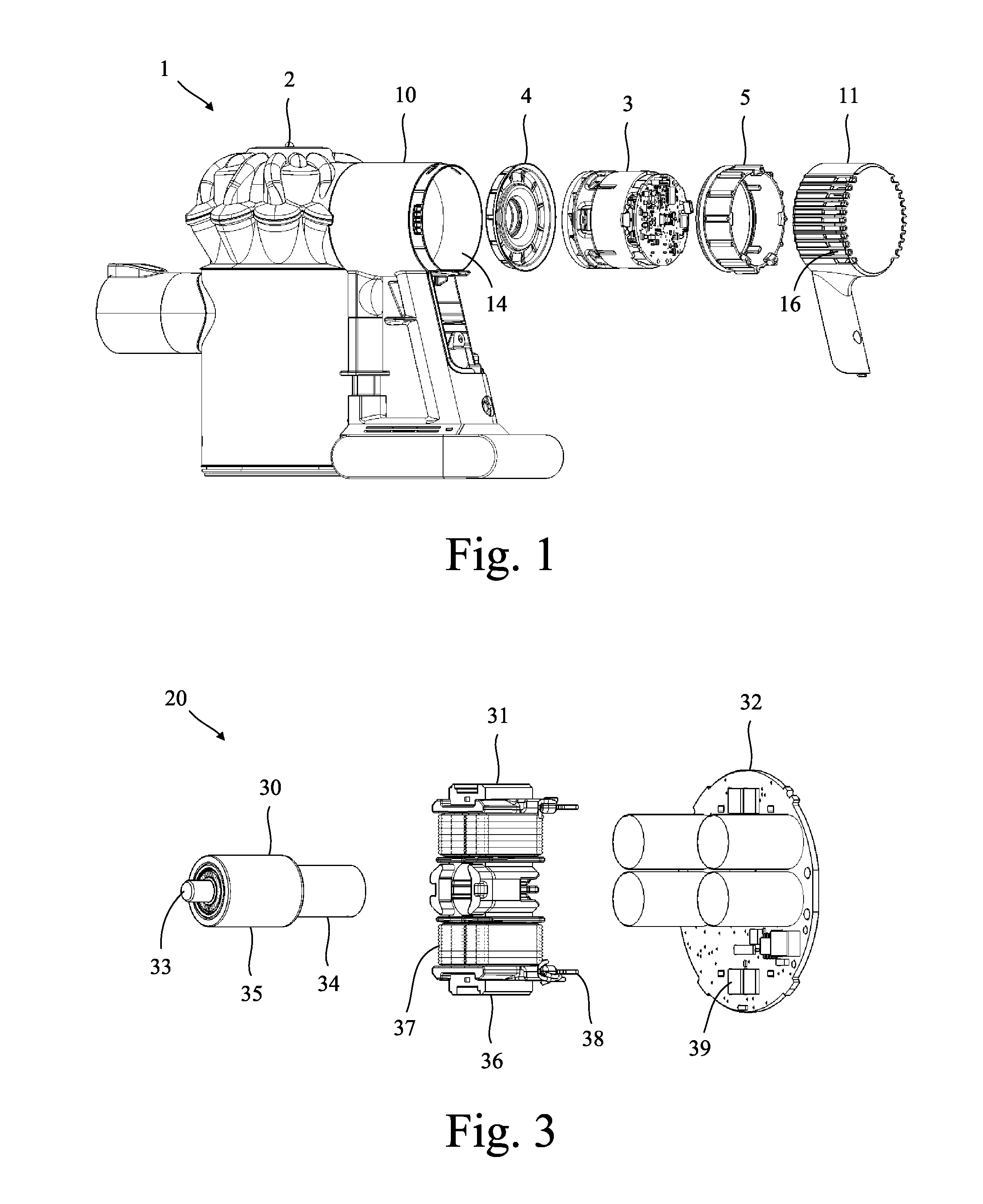
[0019]The product 1 of FIG. 1 comprises a housing 2, a compressor 3, an axial mount 4 and a radial mount 5. Each of the mounts 4,5 is located between the housing 2 and the compressor 3 and acts to isolate the housing 2 from vibration generated by the compressor 3. In this particular example, the product 1 is a handheld vacuum cleaner.

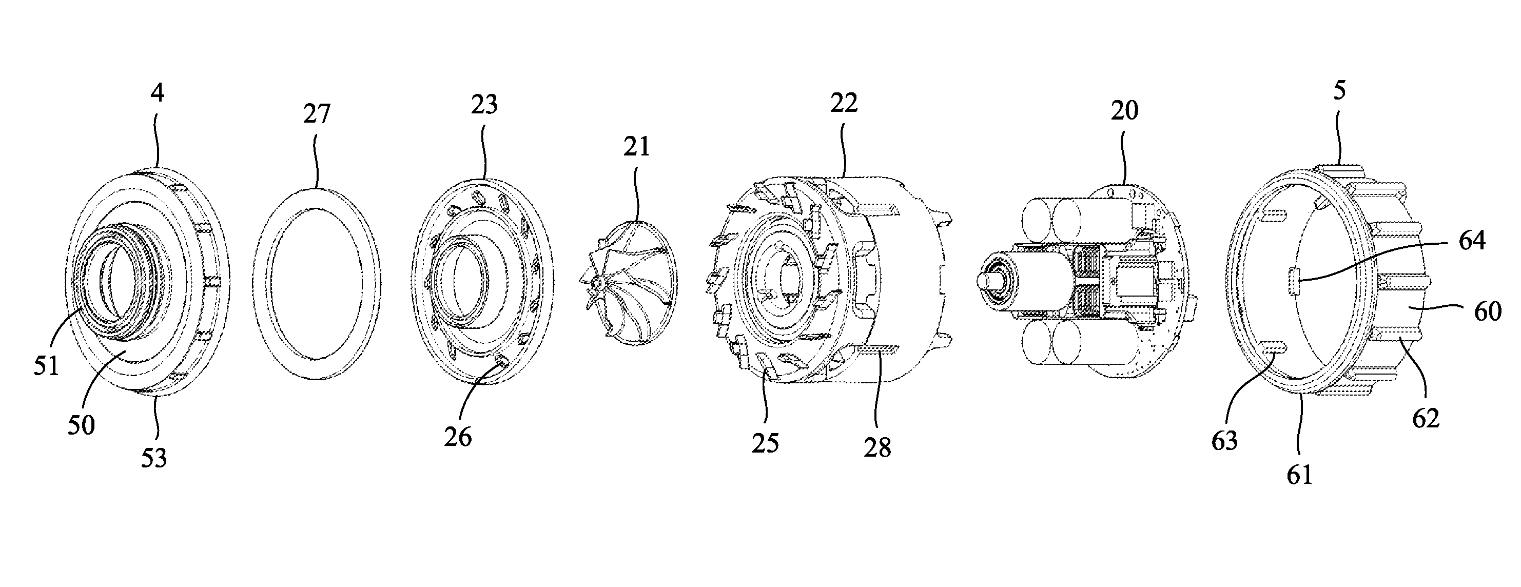
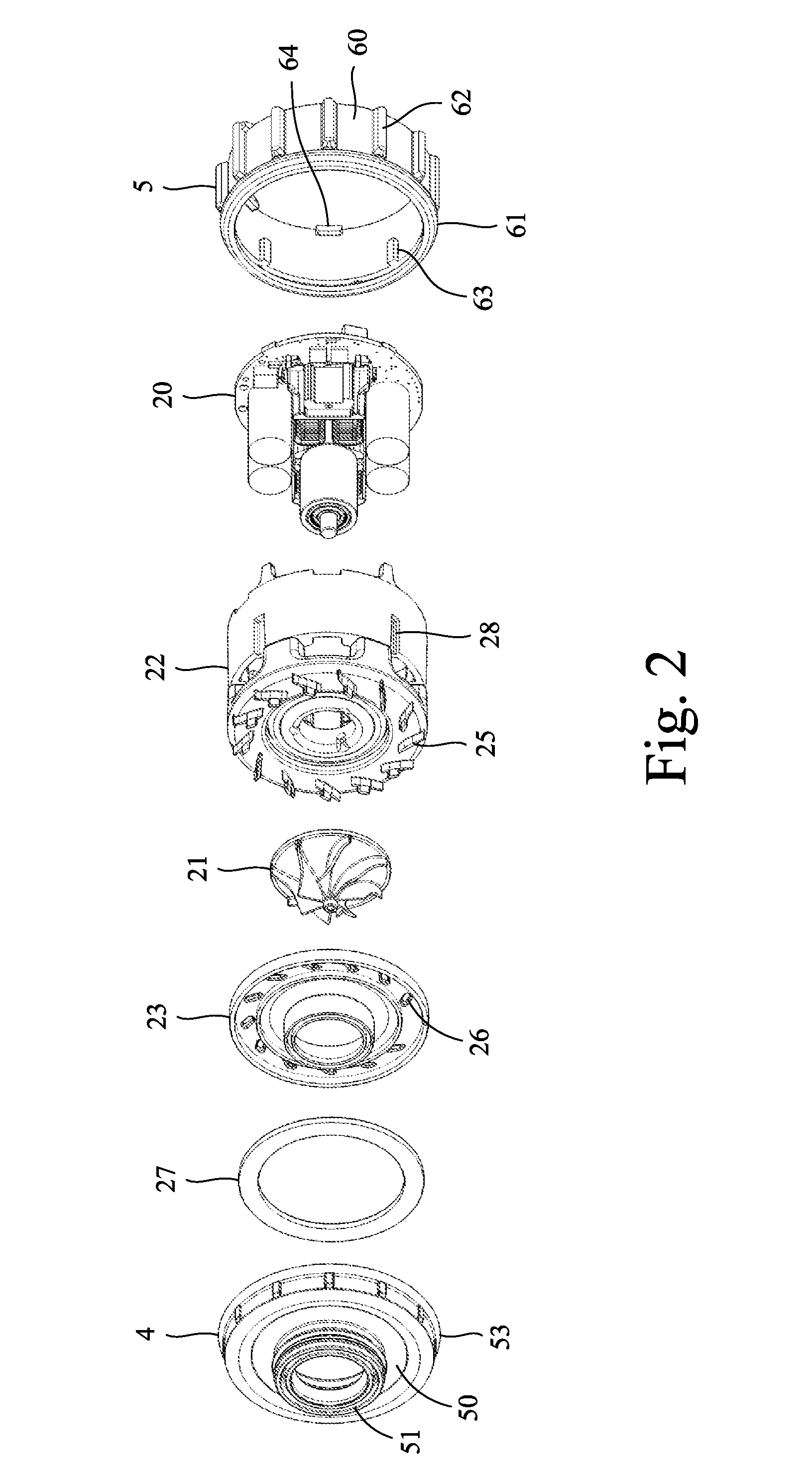
[0020]Referring now to FIGS. 2 and 3, the compressor 3 comprises an electric motor 20, an impeller 21, a frame 22 and a shroud 23.

[0021]The motor 20 comprises a rotor assembly 30, a stator assembly 31 and a circuit assembly 32. The rotor assembly 30 comprises a shaft 34 to which a rotor core 35 and a bearing assembly 36 are attached. The stator assembly 31 comprises a pair of stator cores 37 around which electrical windings 38 are wound. The windings 38 are connected to the circuit assembly 32 via terminal connectors, which also act to secure the circuit assembly 32 to the stator assembly 31. The rotor assembly 30 and the stator assembly 31 are each sec...


PUM


Abstract

A vibration isolation mount for a compressor that is formed of an elastomeric material and includes a sleeve, tapered studs or axial ribs spaced around the sleeve, and a lip seal extending around the sleeve. The mount is intended to be located between a compressor and a housing. The studs or ribs then deform to isolate the housing from radial vibration of the compressor, and the lip seal creates an annular seal between the housing and the compressor.

Description

REFERENCE TO RELATED APPLICATION[0001]This application claims priority of United Kingdom Application No. 1308089.0, filed May 3, 2013, the entire contents of which are incorporated herein by reference.FIELD OF THE INVENTION[0002]The present invention relates to a vibration isolation mount for a compressor.BACKGROUND OF THE INVENTION[0003]A compressor may be mounted within a housing by o-rings that surround the compressor. During operation of the compressor, the o-rings deform to isolate the housing from vibration of the compressor. In addition, the o-rings create a seal between the compressor and the housing. A problem with this arrangement is that, relatively speaking, the housing is poorly isolated from the compressor. That is to say that a significant amount of vibration generated by the compressor continues to be transmitted to the housing.SUMMARY OF THE INVENTION[0004]The present invention provides a vibration isolation mount for a compressor, the mount being formed of an elast...

Claims


Application Information

Patent Timeline
IPC IPC(8): F04D29/66
CPCF04D29/668A47L5/24A47L9/0081A47L9/22F04D25/06F04D29/162F04D29/5806F04D29/5813H02K5/24H02K9/06
Inventor LAMB, JAMES HOPE
Owner DYSON TECH LTD
Why Eureka
Try Eureka