Hydraulic control system for automatic transmission

a control system and automatic transmission technology, applied in the direction of gearing control, gearing element control, belt/chain/gearing, etc., can solve the problems of significant fluctuation of hydraulic pressure, worsening of pressurized fuel pulsation, and affecting the operation of automatic transmission, so as to reduce control, the effect of reducing the frequency of drive signal

Inactive Publication Date: 2014-11-06
TOYOTA JIDOSHA KK
View PDF7 Cites 1 Cited by
  • Summary
  • Abstract
  • Description
  • Claims
  • Application Information

AI Technical Summary

Benefits of technology

[0010]The present invention has been conceived noting the foregoing technical problems, and it is an object of the present invention is to provide a hydraulic control system for an automatic transmission configured to prevent a changes in a speed ratio and a belt clamping pressure by suppressing a pulsation of hydraulic pressure applied to pulleys.
[0022]Thus, the pressure pulsation induced by the drive signal is prevented from entering into resonance with the pulsation resulting from rotating the pulleys. For this purpose, a process for determining the frequency of the drive signal (i.e., the drive frequency) may be simplified by merely determining the drive frequency to be coprime to a frequency of the vibrations resulting from rotating the pulleys.
[0024]In the automatic transmission to which the present invention is applied, the drive pulley and the drive pulley are rotated by the belt at a speed in accordance with a speed ratio. Therefore, the pressure pulsation in the hydraulic chamber of the drive pulley can be efficiently suppressed by determining the drive frequency of the control valve communicated therewith to be out of phase to the frequency of the pressure pulsation resulting from rotating the drive pulley, and the frequency of the pressure pulsation in the hydraulic chamber of the driven pulley. Alternatively, the pressure pulsation in the hydraulic chamber of the driven pulley can be efficiently suppressed by determining the drive frequency of the control valve communicated therewith to be out of phase to the frequency of the pressure pulsation resulting from rotating the driven pulley, and the frequency of the pressure pulsation in the hydraulic chamber of the drive pulley.
[0025]Further, the response and the stability of the feedback control can be prevented from being deteriorated by altering the control gains in accordance with the drive frequency.

Problems solved by technology

Given that a drive frequency coincides with a natural resonance frequency of the fuel pressure regulating valve during the PWM control of the valve, a pulsation of the pressurized fuel is worsened.
However, a pressure in the hydraulic chamber may be fluctuated by such delivery and drainage of the hydraulic fluid to / from the hydraulic chamber.
However, if the vibration frequency of the hydraulic fluid in any of the hydraulic chamber coincides with the vibration frequency of the hydraulic fluid delivered or drained to / from the hydraulic chamber, the resonance may be caused thereby fluctuating the hydraulic pressure significantly.
However, the device described therein is not configured to reduce a resonance of the hydraulic fluid governing the clamping pressure, and resultant changes in the speed ratio and the clamping pressure.
Likewise, it is also difficult to reduce the change in the speed ratio resulting from the pulsation of the hydraulic fluid by the control system taught by Japanese Utility Model Laid-Open No. 63-48637.
Therefore, an operating speed of the engine may be deviated from a target value thereby deteriorating the fuel economy.
Therefore, if a delivery and a drainage of the hydraulic fluid are carried out at significantly different timings so that pressure fluctuations induced by the delivery of the fluent and induced by the drainage of the fluent have no influence on each other, it is difficult to suppress the pulsation of the hydraulic fluid by the device taught by Japanese Patent Laid-Open No. 2000-291474.

Method used


Image

  • Hydraulic control system for automatic transmission
  • Hydraulic control system for automatic transmission
  • Hydraulic control system for automatic transmission

Examples


Embodiment Construction

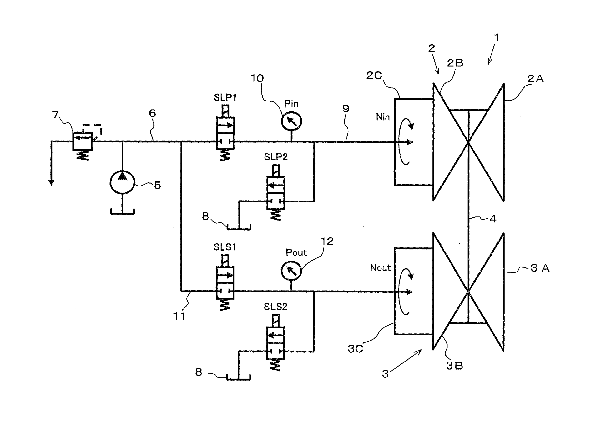
[0031]For example, the present invention is applied to an automatic transmission such as a belt-driven continuously variable transmission. Referring now to FIG. 1, there is shown a structure of the belt-driven continuously variable transmission 1. As shown in FIG. 1, the belt-driven continuously variable transmission 1 is comprised of a primary pulley 2 as a drive pulley, a secondary pulley 3 as a driven pulley, and a belt 4 running between those pulleys 2 and 3. Specifically, the primary pulley 2 is comprised of a fixed sheave 2A integrated with a rotary shaft (not shown), and a movable sheave 2B allowed to move closer to and away from the fixed sheave 2A. Sheaves 2A and 2B have inwardly facing conical surfaces to form a belt groove. In addition, the movable sheave 2B is provided with a hydraulic chamber 2C on its back side (i.e., on an opposite side of the conical surface) for hydraulically pushing the movable sheave 2B toward the fixed sheave 2A.

[0032]The secondary pulley 3 is st...


PUM


Abstract

A hydraulic control system for an automatic transmission, in which a belt is applied to at least one pair of pulleys, and in which widths of belt grooves of the pulleys, or pressures to clamp the belt by the pulleys are controlled by hydraulic pressures applied to hydraulic chambers of the pulleys. The hydraulic control system is comprised of: a control valve that controls a delivery and a drainage of hydraulic fluid to / from the hydraulic chamber; and a drive frequency setting means that determines a drive frequency of a drive signal for actuating the control valves in such a manner that a phase of a local maximum value of amplitude of the drive signal is shifted from a phase of a local maximum value of amplitude of vibrations resulting from rotating the pulleys.

Description

TECHNICAL FIELD[0001]The present invention relates to a hydraulic control system for controlling a hydraulic fluid delivered and drained to / from drive and the driven pulleys of a belt-driven continuously variable transmission.BACKGROUND ART[0002]A belt-driven continuously variable transmission is comprised of a drive pulley, a driven pulley and a belt driving between those pulleys. In the belt-driven continuously variable transmission, a speed ratio is changed by hydraulically varying a groove width of those pulleys. Meanwhile, a torque transmitting capacity of the belt-driven continuously variable transmission is changed in response to an input torque by hydraulically changing a belt clamping load (i.e., a clamping pressure) of the pulley. The belt-driven continuously variable transmission is mounted on an automobile, and the speed ratio thereof is controlled in such a manner that an engine is operated at a speed possible to minimize fuel consumption rate. The clamping pressure is ...

Claims


Application Information

Patent Timeline
Patent Type & Authority Applications(United States)
IPC IPC(8): F16H61/02F16H61/662
CPCF16H61/662F16H61/0267F16H61/66259F16H57/0006F16H2061/0255
Inventor KIMURA, KENTAHATTORI, YUJIINAGAWA, TOMOKAZUINAGAKI, TAKAFUMINAGASATO, YU
Owner TOYOTA JIDOSHA KK
Why Eureka
Try Eureka