Hose clamp and method of manufacturing the same

a technology of hose clamps and hoses, which is applied in the direction of hose connections, metal-working equipment, haberdashery, etc., can solve the problems of difficult pinching operation on the two pinching portions, unbalanced pinching operation, and difficulty in performing pinching operation on the above hose clamps, so as to facilitate pinching operation and expand the operation area

Active Publication Date: 2014-11-13
TOGO SEISAKUSYO CORP
View PDF12 Cites 9 Cited by
  • Summary
  • Abstract
  • Description
  • Claims
  • Application Information

AI Technical Summary

Benefits of technology

[0014]there is formed, between the proximal region and the expansion region, at least one of a folding edge allowing folding of the expansion region to a non-interference position where it does not interfere with the first end portion or the second end portion constituting the mating side when the plate material is bent along the X-axis, and a connection edge for connecting the expansion region formed separately from the proximal region.
[0015]According to the present invention, when the strip-like plate material is bent into a ring-like shape, the expansion region is previously folded with respect to the proximal region via the folding edge, or the proximal region is previously caused to stay singly, in at least one of the first pinching operation surface and the second pinching operation surface. By doing so, it is possible for the plate material to avoid the interference when it is bent along the X-axis. After this, the expansion region is unfolded, or the separate expansion region is connected to the singly staying proximal region via the connection edge, whereby it is possible to enlarge the operation area of at least one of the first pinching operation surface and the second pinching operation surface. As a result, it is possible to facilitate the pinching operation.
[0022]In this construction, when the plate material is bent into a ring-like shape along the X-axis, the expansion region is folded at the folding edge, or the proximal region stays singly, so that the second pinching operation surface allows its insertion without involving interference with the hole edge of the through-hole. After the insertion, the expansion region is unfolded to be developed outwardly in the width direction, or the expansion region is connected to the side edge of the proximal region staying singly via the connection edge, and the outer width dimension of the second pinching operation surface expands in the width direction. As a result, the outer width of the second pinching operation surface is made larger than the opening width of the through-hole, so that it is possible to attain a satisfactory pinching-operability. In addition, the hose clamp as a whole is substantially in line symmetry with respect to the X-axis, so that it is also possible to make the stress applied to the hose clamp well-balanced with respect to the X-axis.
[0028]In this construction, when bending the plate material along the X-axis into a ring-like configuration, both pinching operation surfaces can pass the lightening regions. After the passing, the expansion regions are unfolded, or are connected to the proximal regions to cross the X-axis in a staggered fashion with respect to each other. That is, the pinching operation surfaces are both enlarged in width, whereby it is possible to provide a satisfactory pinching-operability. In addition, the hose clamp as a whole is substantially in point symmetry with respect to the Y-axis, so that it is possible to balance the stress applied to the hose clamp with respect to the Y-axis.
[0030]In this construction, when the operator performs pinching operation on the first and second pinching operation surfaces, the finger of the operator is applied to the protrusion, and does not touch the edge portions at the peripheral edges of both pinching operation surfaces, so that there is little danger of the finger being injured.
[0032]In this construction, there are included peripheral edges of both pinching operation surfaces bent toward the opposing surface side due to the escape portions, whereby the peripheral edges constituting the edges of both pinching operation surfaces are spaced away from the finger, so that it is possible for the finger to avoid touching the edge portions. Thus, it is possible to avoid a situation in which the operator suffers injury of his finger.

Problems solved by technology

Thus, due to the restriction by the opening width of the through-hole, it is rather difficult for the second pinching portion to secure a sufficient width dimension.
Thus, the width of the second pinching portion is rather small, and the difference in width dimension between the first and second pinching portions is large, so that the pinching operation on the two pinching portions is likely to be rather unbalanced.
As a result, it is rather hard to perform pinching operation on the above hose clamp.

Method used


Image

  • Hose clamp and method of manufacturing the same
  • Hose clamp and method of manufacturing the same
  • Hose clamp and method of manufacturing the same

Examples


embodiment 1

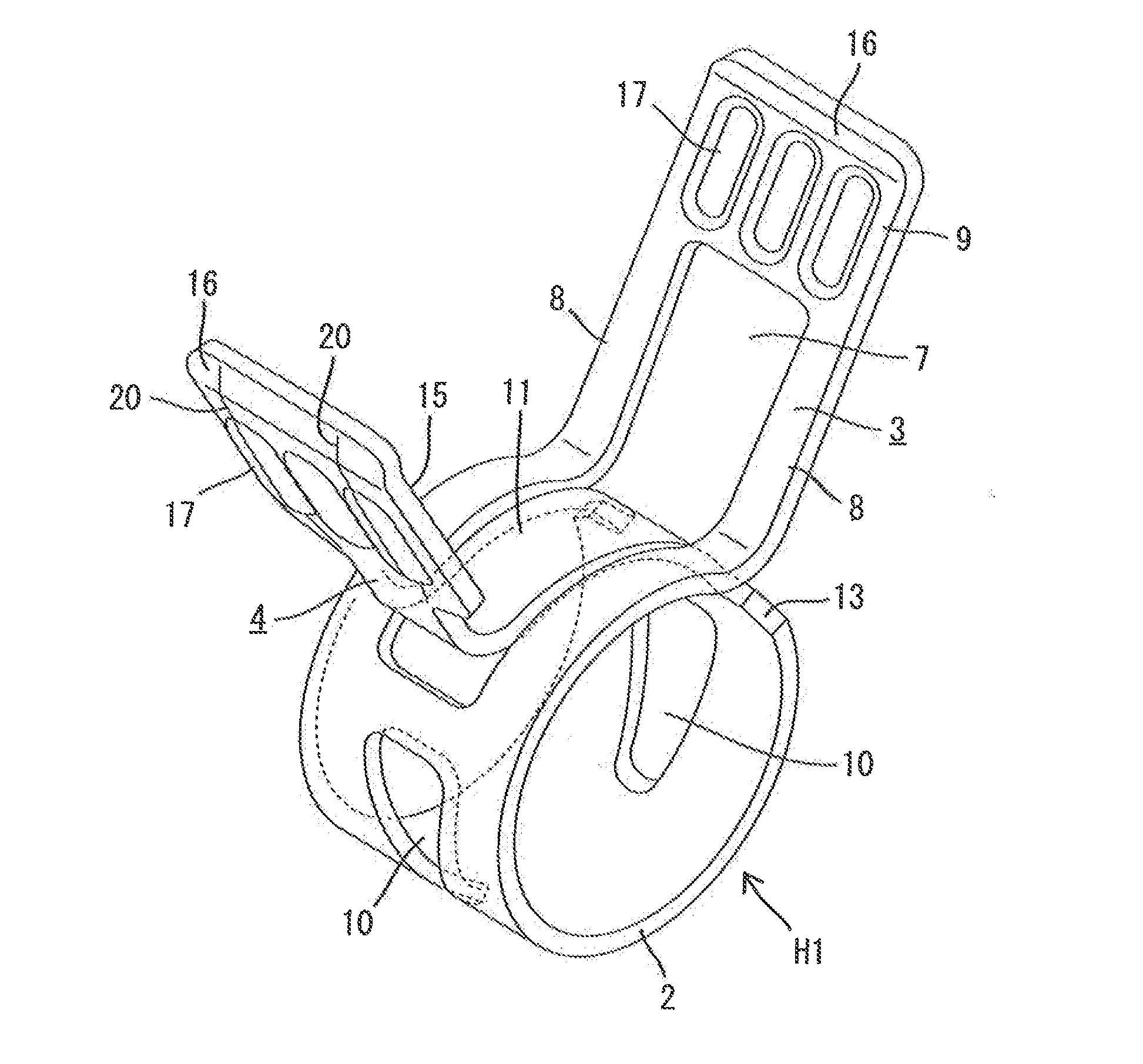
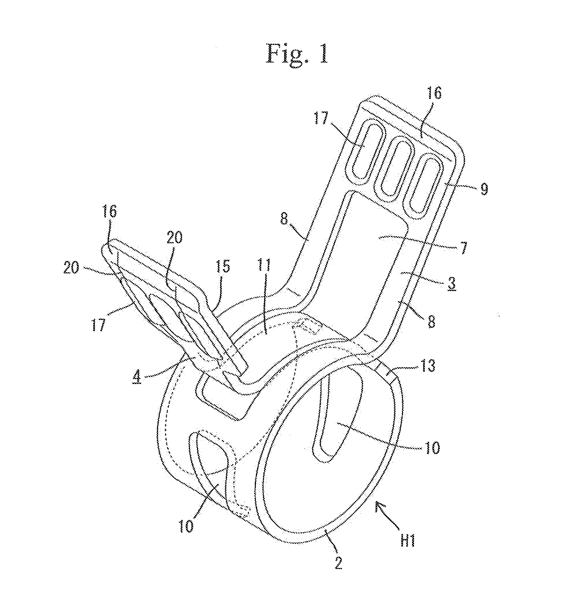
[0063]In the following, embodiment 1 of the present invention will be described with reference to FIGS. 1 through 6. A hose clamp H1 according to the present embodiment is formed integrally of a plate material consisting of spring steel. As shown in FIG. 4, in the developed state, the hose clamp is formed as a strip extending in the longitudinal direction (along the X-axis direction mentioned below). This strip-like plate material 1 is bent along the X-axis from the developed state into a ring-like configuration to form a tightening portion 2 capable of elastic deformation so as to be reduced and increased in diameter. Both end portions of the hose clamp protrude radially outwards from the tightening portion 2 to respectively constitute first and second pinching portions 3 and 4. The two pinching portions 3 and 4 are opposite each other in the peripheral direction.

[0064]As shown in FIG. 4, the plate material 1 for forming the hose clamp H1 is formed symmetrically with respect to the...

embodiment 2

[0079]FIGS. 7 and 8 show embodiment 2 of the present invention,

[0080]As shown in FIG. 7, the hose clamp H2 according to embodiment 2 has no through-hole 7. In the hose clamp H2 of the present embodiment, a first pinching operation surface 30 and a second pinching operation surface 31 cross each other in the axial direction in a staggered manner. Although the triangular windows 10 of embodiment 1 are not shown in FIG. 7, they may be provided as in embodiment 1,

[0081]The hose clamp H2 according to embodiment 2 is manufactured by the steps shown in FIG. 8. As shown in FIG. 8(I), a plate material 32 in the developed state is of a configuration in point symmetry with respect to the Y-axis (the developed form shaping step). As shown in FIG. 8(I), one side edge in the longitudinal direction of the plate material 32 (the side edge shown on the lower side in the drawing) extends straight along the X-axis from the distal end of a second end portion 34, and reaches a predetermined position bey...

embodiment 3

[0090]FIG. 9 shows a second pinching operation surface 50 of a hose clamp H3 according to embodiment 3 of the present invention; the first pinching operation surface can be formed in the same manner. In the hose clamp H3 of embodiment 3, expansion regions 52 are separate from a proximal region 51 when the plate material is in the developed state. That is, in embodiment 3, the proximal region 51 is caused to singly enter a through-hole (not shown), and then the pair of expansion regions 52 are mounted to both side edges in the width direction of the proximal region 51 by welding or the like via connection edges 53.

[0091]In the present embodiment, the width dimension of the proximal region 51 alone is smaller than the minimum opening width of the through-hole (not shown); however, the outer width dimension of the second pinching operation surface 50 in the state in which both expansion regions 52 have been attached is set to be larger than the maximum opening width of the through-hole...


PUM

PropertyMeasurementUnit
shapeaaaaaaaaaa
symmetryaaaaaaaaaa
widthaaaaaaaaaa

Abstract

The pinching operation is facilitated. A hose clamp (H1) is formed by bending a strip-like plate material (1) into a ring-like configuration, and includes a first end portion (5) having a first pinching operation surface (9), and a second end portion (6) having a second pinching operation surface (15). A through-hole (7) is open near the center in the longitudinal direction of the first pinching operation surface (9). At the time of bending into ring-like configuration, expansion regions (19) arranged at both side portions in the width direction of the second pinching operation surface (15) are folded at folding edges (20) with respect to a proximal region (18), whereby the second pinching operation surface (15) is narrowed in the width direction and can enter the through-hole (7). After bending into ring-like configuration, the expansion regions (19) are unfolded at the folding edges (20) and regain a widened state.

Description

TECHNICAL FIELD[0001]The present invention relates to a hose clamp and a method of manufacturing the same.BACKGROUND ART[0002]Patent Document 1 discloses a hose connection device for tightening a connection portion between a hose and a pipe. The hose connection device disclosed in the document has a hose clamp formed in a ring-like configuration. The hose clamp is formed by bending a strip-like plate spring material into a ring-like shape; at one longitudinal end side thereof there is formed forked a first end portion where an elongated-hole-like through-hole is open. The range of the first end portion including the through-hole is bent in the radial direction to form a first pinching portion. At the other end side of the hose clamp, there is formed a second end portion of a smaller width than the opening width of the through-hole. The second end portion is bent in the radial direction so as to form a second pinching portion opposite the first pinching portion.[0003]The above hose c...

Claims


Application Information

Patent Timeline
Patent Type & Authority Applications(United States)
IPC IPC(8): F16L33/03B21D53/36
CPCF16L33/03B21D53/36Y10T24/1418
Inventor OZAWA, TAKEHIKO
Owner TOGO SEISAKUSYO CORP
Why Eureka
Try Eureka