Attachment guide comb conduit

a comb and guide wire technology, applied in the direction of hair combs, metal working devices, manufacturing tools, etc., can solve the problems of lack of advantage, loss of support, bending to one side, etc., and achieves reduced structure, effective, and minimal noise or vibration

Inactive Publication Date: 2014-11-13
MICHEL MATTHEW JUSTIN
View PDF13 Cites 39 Cited by
  • Summary
  • Abstract
  • Description
  • Claims
  • Application Information

AI Technical Summary

Benefits of technology

[0037]The second such embodiment is a means of organizing a set of attachment guide combs by attaching them to a series of interconnected compatible forms. This embodiment is elaborated on to include the interconnected blades being free standing, arranged along a contour, flexibly interconnected, connected to and within a container, and including compatible forms with flexibility and reduced structure. The applications for organizing attachment guide combs have been expanded by the many embodiments which have become possible as a result of the central inventive concept of employing a dummy blade.
[0038]The third embodiment is a conventional barber scissor fastened to a dummy clipper head to which the attachment guide combs can be attached. Once assembled, a scissor comb is created which is safe (the comb guarding the blade), and an effective means of trimming the hair to a uniform length with minimal noise or vibration.
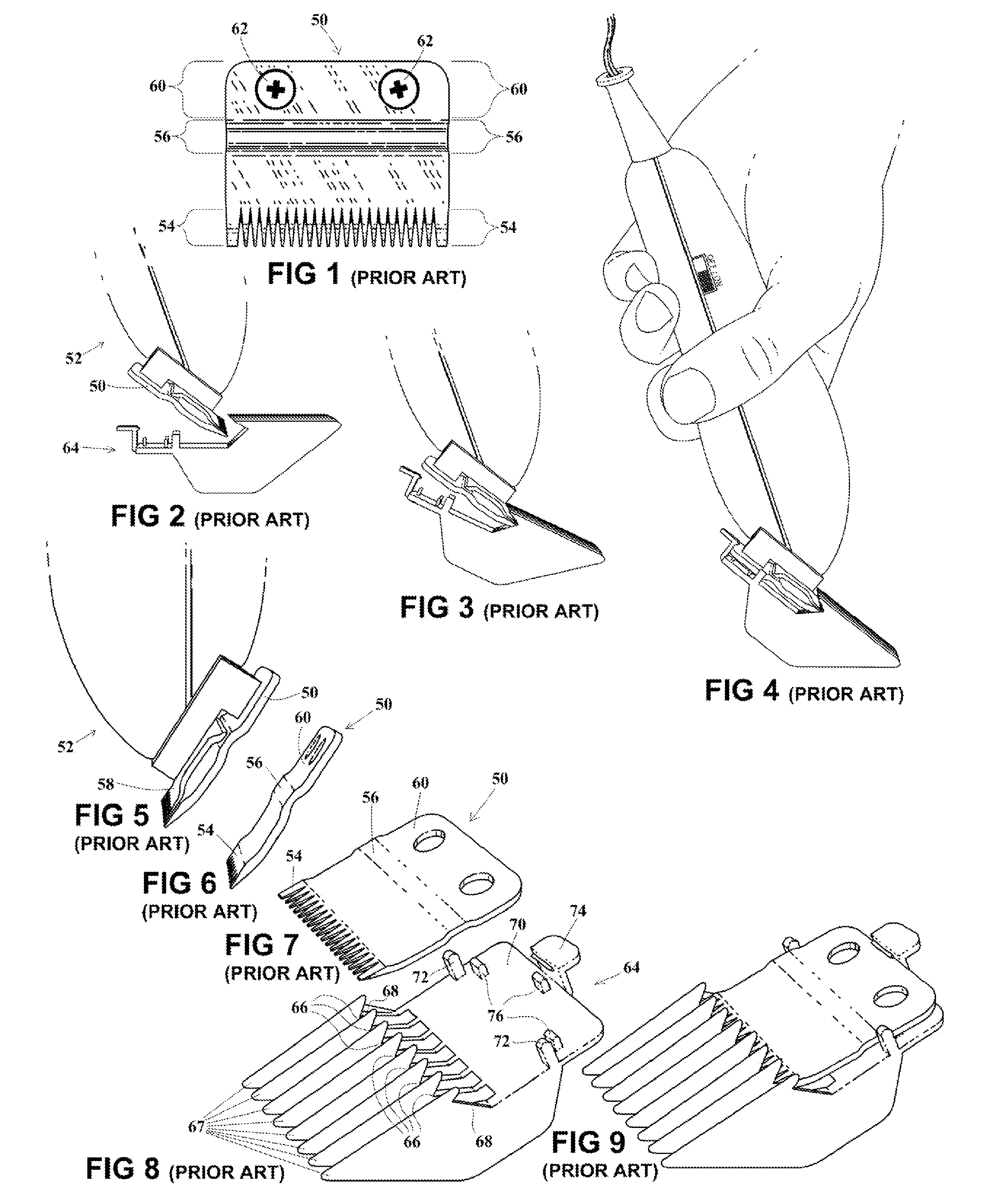
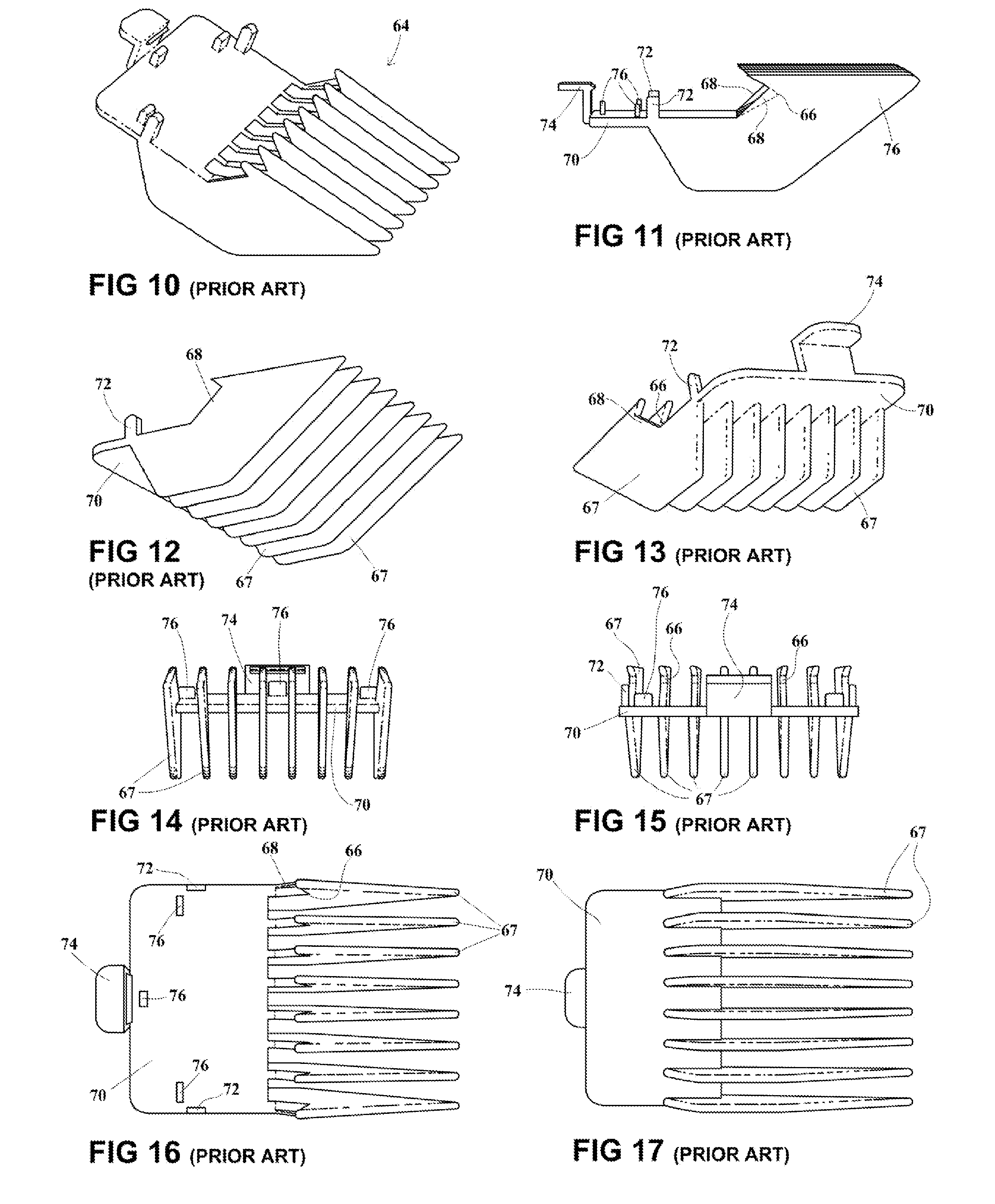
[0040]The attachment guide combs typically have a V shaped groove as part of their attaching means. Both the dummy clipper heads for the razor comb and the scissor comb employ a novel method of engagement with the V shaped groove of the attachment guide comb which has several benefits and broader applications. Instead of engaging with the vertex of this groove they engage it along both the upper and lower portions so as not to extend fully into the groove.

Problems solved by technology

There is one problem with the means by which the attachment guide combs attach to the stationary blade of the hair clipper.
Unfortunately the attachment guide comb's teeth, being flexible, can slip off the supporting small metal teeth of the guide comb, losing its support and bending to one side.
This design was not intended to regulate the length of hair cut and lacks this advantage.
All three designs have comb backs at surface level obstructing the path for the uncut hair and would therefore not pull smoothly through the hair.
The Custer design has both a narrow support base and a comb back at surface level and would therefore not work well being pulled through the hair.
If the teeth are too long the vacuum will lose suction through the gap between the surface of the hair and the vacuum inlet.
It is of course not possible in this case for the vacuum inlet's opening to have an edge within the V-shaped groove of the attachment guide comb as the blades of the hair clipper occupy this space.
Though limited and complex, these designs would be effective on different hair thickness.
Though all the above liquid dispensing combs are effective, each features a comb of a specific length and lacks length adjustment.
The storage and organization the attachment guide combs within the hair clipper kit within a case or bag has always represented a problem.
This has meant that the attachment guide combs easily shift and move around in a container and are not easily contained.
None of the attempts to organize and store attachment guide combs thus far have employed any means beyond those used in storing any other object.
Without additional securing means the combs could easily fall out while being transported.
These holders are also bulky and are not customizable, the number, type and location of attachment guide combs being fixed.

Method used


Image

  • Attachment guide comb conduit
  • Attachment guide comb conduit
  • Attachment guide comb conduit

Examples


first embodiment

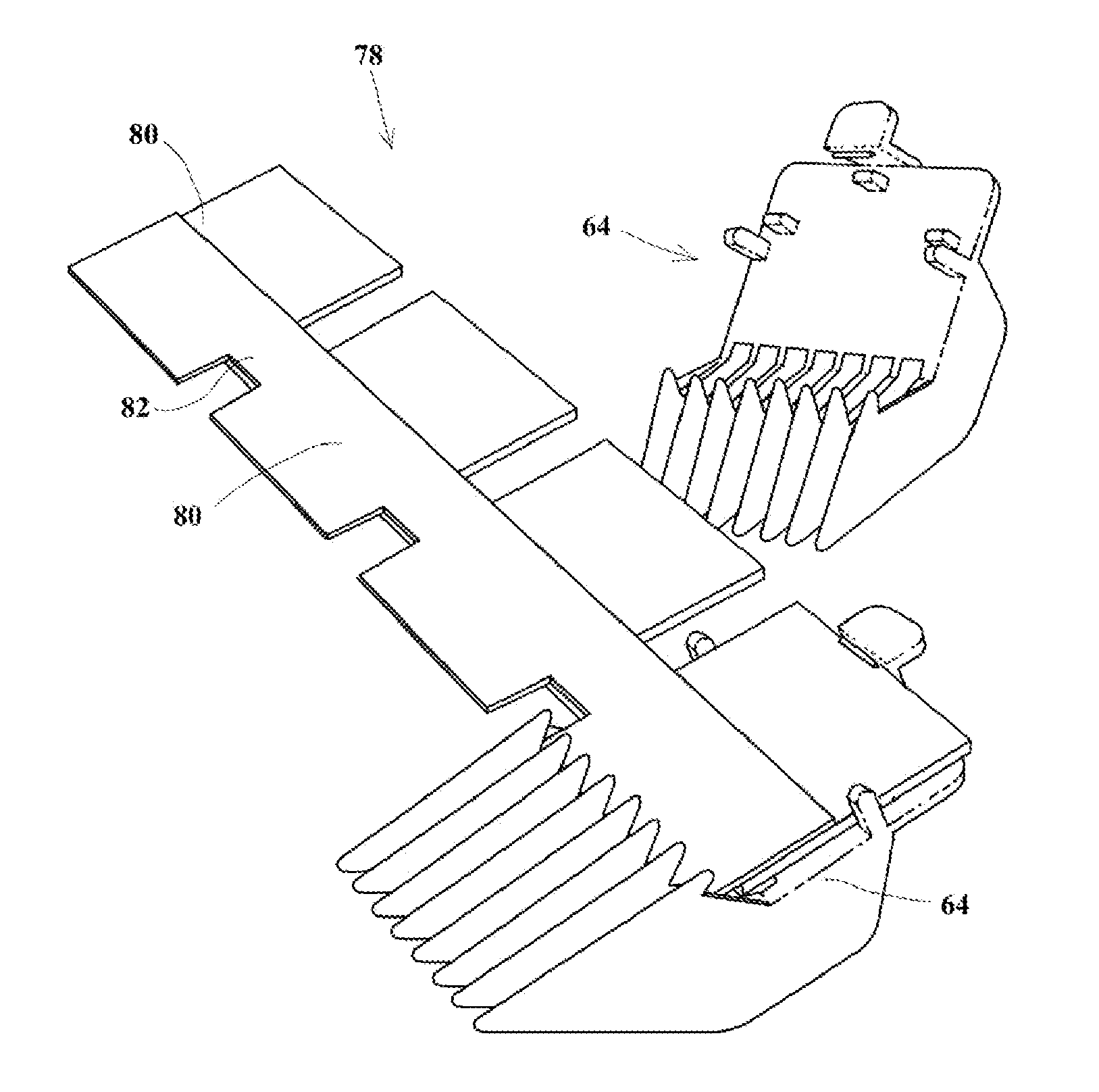
[0133]the invention is a comb organizer 78 and is shown in FIGS. 20 and 21. The organizer 78 consists of four adjacent dummy blades 80 shown separately in FIGS. 18 and 19.

[0134]FIGS. 18 and 19 show the dummy blade 80 above the stationary blade 50 to which it partially conforms. The dummy blade 80 includes a thin rectangle 82 which is 0.025 inches thick, and 1.8 inches by 0.75 inches, overlapping and bonded to a thick rectangle 84 which is 0.075 inches thick, and 1.8 inches by 1.2 inches. The rectangles overlap by 0.45 inches resulting in a combined rectangle 1.8 inches by 1.5 inches, which conforms to those dimensions of the blade 50.

[0135]The thin leading edge is 0.025 inches higher than the thick rear edge which also conforms to those dimensions of the stationary blade 50. The underside of the thick rectangle 84 is flat for more than 0.5 inches from the rear edge providing a suitable surface for the abutments 76, just as the rear region 60 does of the stationary blade 50 as descri...

second embodiment

[0142]FIGS. 22-26 show the invention which is the scissor comb 90. The scissor comb 90 includes a barber's scissor 92 with a single counter-sunk hole 94 drilled into one blade 1.5 inches from the tip. A screw 96 secures the scissor 92 to a dummy blade B 98. The dummy blade B 98 allows the attachment of the attachment guide comb 64. The scissor comb 90 can then be pulled through hair and employed cutting the hair to a uniform thickness.

[0143]The dummy blade B 98 is shown from two angles in FIG. 22, from the side and in perspective. It is 1.8 inches wide, as is the stationary blade 50. It is 1.4 inches from its beveled leading edge to its rear edge, where the real stationary blade 50 is 1.5 inches. This shorter length is due to the novel means by which dummy blade B 98 engages the V shaped groove 66 which is indicated by dotted lines in FIG. 25. Rather than contacting the groove 66 at its vertex, as the stationary blade 50 does, it instead makes dual contact, an upper contact along it...

third embodiment

[0150]the present invention, the razor comb 106 is shown in FIGS. 27-30. Referring to FIG. 28 which is an exploded view of the four pieces of the razor comb 106 (other than the attachment guide comb 64), the razor comb 106 consists of a handle 108, a top plate 110, a razor blade 112, and a base plate 114 which when fully assembled connect with the attachment guide comb 64.

[0151]The razor 112 is held in position on the base plate 114 by two cylindrical protrusions 116 which are inserted into apertures 118 of said razor 112. The top plate 110 is then placed over the base plate 114 passing the threaded post 119 of the base plate 114 through the hole 122 of the top plate 110 and finally inserting the cylindrical protrusions 116 into corresponding cylindrical depressions (not shown) in the underside of the top plate 110. The handle 108, which has a threaded socket (not shown), is then threaded onto the post 119 and the four pieces are thereby secured together.

[0152]The top plate 110 and ...


PUM

PropertyMeasurementUnit
thicknessaaaaaaaaaa
thicknessaaaaaaaaaa
widthaaaaaaaaaa

Abstract

A dummy hair clipper head, or dummy blade, which is a form conforming to those dimensions of a hair clipper's stationary blade which are necessary for its compatibility with attachment guide combs, is employed in a conduit comb which comprises a form configured to allow air or liquid to pass through the form and between the teeth of the attachment guide comb, whereby an attachment guide comb can be employed in vacuuming, drying, washing and treating hair. The form can be connected in turn to a bottle, air hose, or faucet to allow for the transmission of air or liquid through the comb. The use of the form also makes possible a variety of new uses for attachment guide combs including a scissor comb, razor comb, and comb organizer.

Description

CROSS-REFERENCE TO RELATED APPLICATION[0001]This application is a continuation in part of U.S. patent application Ser. No. 12 / 422,993, filed on Apr. 14, 2009, which was a continuation-in-part application of parent application Ser. No. 11 / 470,256, filed Sep. 6, 2006, the entire disclosure of which is incorporated by reference for any and all purposes.FIELD OF THE INVENTION[0002]The present invention relates to the conduction of fluent material, such as air and liquid, through attachment guide combs, of the type having a V-shaped groove, by their attachment to a compatible form configured for that purpose.BACKGROUND OF THE INVENTION[0003]Before giving the background of the embodiments of the present invention it is first important to understand the background of attachment guide combs of the type having a V-shaped groove and their use with electric hair clippers.[0004]The hair clipper kit found in most homes today includes an electric hair clipper and a set of four to ten attachment g...

Claims


Application Information

Patent Timeline
Patent Type & Authority Applications(United States)
IPC IPC(8): B26B19/38
CPCB26B19/3813B26B13/24B26B19/20B26B19/3806B26B19/3826B26B19/40B26B19/44B26B21/12A45D20/12A45D24/22A45D24/36Y10T29/49826
Inventor MICHEL, MATTHEW JUSTIN
Owner MICHEL MATTHEW JUSTIN
Why Eureka
Try Eureka