Laser drilling without burr formation

a technology of laser drilling and burr formation, which is applied in the direction of turbines, manufacturing tools, mechanical equipment, etc., can solve problems such as possible coating damag

Inactive Publication Date: 2014-11-13
SIEMENS AG
View PDF9 Cites 3 Cited by
  • Summary
  • Abstract
  • Description
  • Claims
  • Application Information

AI Technical Summary

Benefits of technology

[0007]It is therefore an object of the invention to solve the problem mentioned above.

Problems solved by technology

This is time-consuming and may result in damage to a coating which is possibly present.

Method used


Image

  • Laser drilling without burr formation
  • Laser drilling without burr formation
  • Laser drilling without burr formation

Examples


Embodiment Construction

[0014]The figures and the description represent merely exemplary embodiments of the invention.

[0015]FIG. 7 shows a substrate 4 of a component which is machined by means of a laser beam 7.

[0016]Here, the focus is preferably located below the surface 5 of the substrate 4 and the material of the substrate or of the component is evaporated, as indicated by the arrows. In this case, the laser beam does not move within a plane (percussion process), if appropriate perpendicular to the surface 8.

[0017]In another laser process—trepanning (FIG. 8)—the laser beam 7 is guided along a desired shape of the hole 10 to be made.

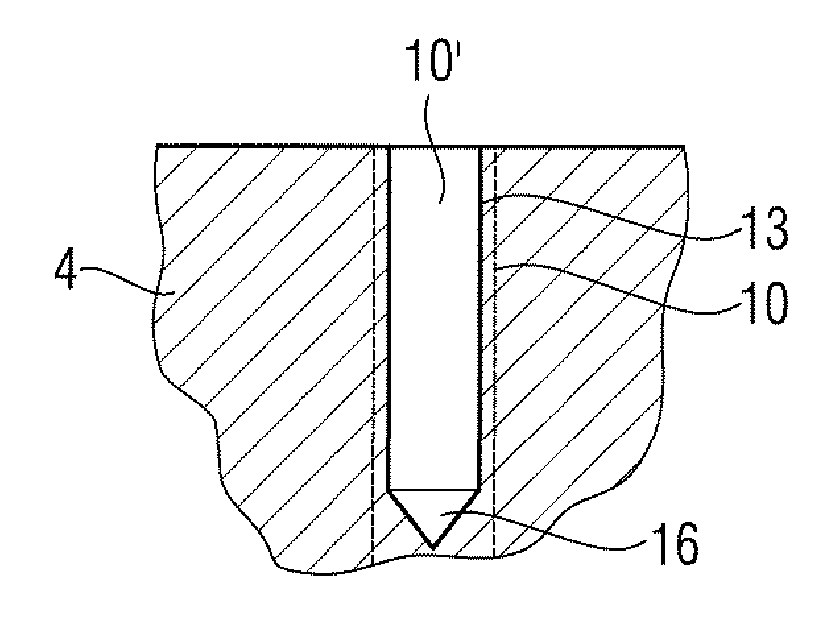
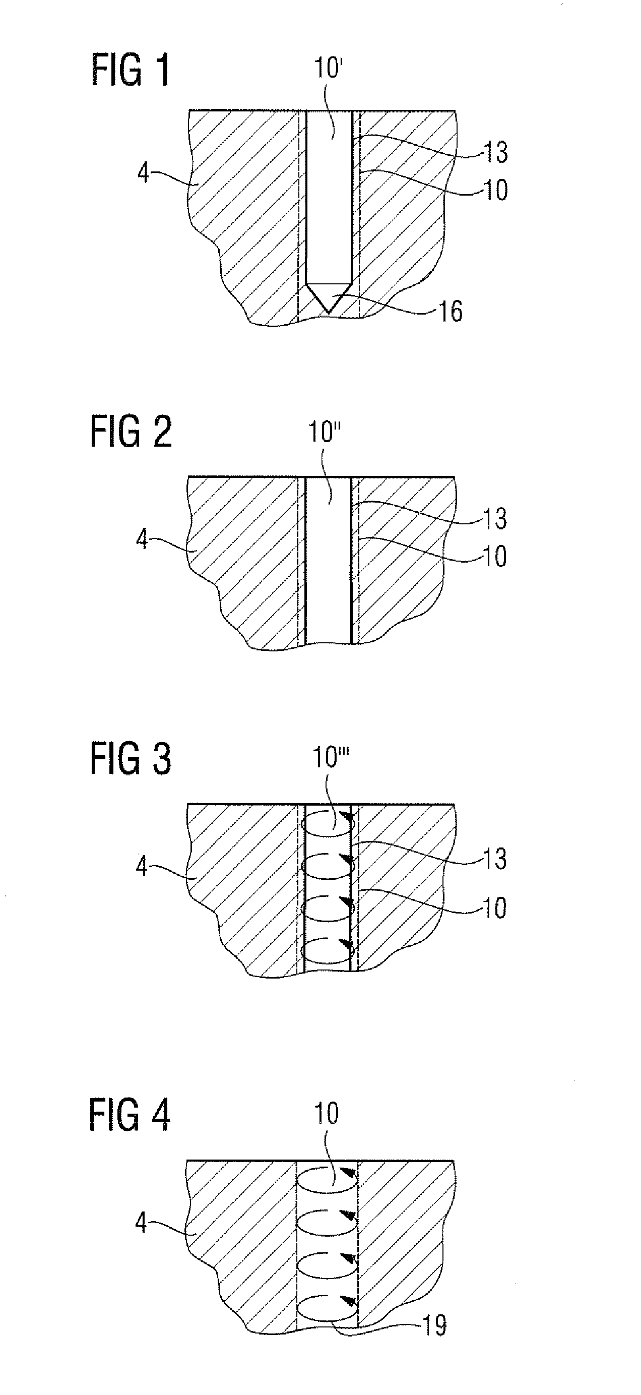
[0018]FIG. 1 shows a first step of the process according to the invention.

[0019]The percussion process is used to produce an intermediate hole 10′. In one embodiment, the intermediate hole 10′ is a blind hole, down to a defined depth, preferably at least 40%, very preferably at least 60%, preferably 90% or 95% of the final drilling depth for a hole 10.

[0020]Here, the cross se...


PUM

PropertyMeasurementUnit
diameteraaaaaaaaaa
timeaaaaaaaaaa
shapeaaaaaaaaaa

Abstract

A process for making a hole into a substrate by at least one laser includes a first step which involves producing at least one intermediate hole with a diameter which is smaller than a final diameter of a final hole to be produced. The intermediate hole with the smaller diameter is a through-hole. The intermediate hole is produced by percussion process. The process further includes a second step which involves producing the final hole having the final diameter. The final hole is produced by machining the intermediate through-hole by a trepanning process so that the final diameter of the final hole is achieved.

Description

CROSS REFERENCE TO RELATED APPLICATIONS[0001]This application is a continuation of U.S. patent application Ser. No. 13 / 098,539 filed May 2, 2011. This U.S. patent application Ser. No. 13 / 098,539 claims priority of European Patent Office application No. 10004709.1 EP filed May 4, 2010. All of the applications are incorporated by reference herein in their entirety.FIELD OF INVENTION[0002]The invention relates to the laser drilling of components.BACKGROUND OF INVENTION[0003]It is prior art to use a laser for producing holes.[0004]The use of a laser involves the percussion and the trepanning[0005]Particularly when producing holes in metallic substrates, burrs are formed at the bore outlet owing to the evaporation of the substrate material, even when the surface is provided with surface protection.[0006]These burrs have to be removed with additional expenditure, for example by means of grinding. This is time-consuming and may result in damage to a coating which is possibly present.SUMMAR...

Claims


Application Information

Patent Timeline
Patent Type & Authority Applications(United States)
IPC IPC(8): B23K26/38
CPCB23K26/386B23K26/388B23K2201/001B23K26/389B23K2101/001
Inventor MASSA, ANDREAOPPERT, ANDREAS
Owner SIEMENS AG
Why Eureka
Try Eureka