Garment assembly and release apparatus and method

a technology for garments and releasing devices, applied in the direction of buckles, snap fasteners, scarves, etc., can solve the problems of complex systems, heavy vests, and significant time and familiarity, and achieve convenient and simple manual pulling motion, fast and simple effect, and easy grasping and moving

Active Publication Date: 2014-11-13
FIRSTSPEAR TUBES LLC
View PDF10 Cites 20 Cited by
  • Summary
  • Abstract
  • Description
  • Claims
  • Application Information

AI Technical Summary

Benefits of technology

[0012]In a preferred manner of operation, with the C-shaped clip attached to the first location on the garment, and the pin attached to the second location, the pin can be slidably inserted into the channel of the C-shaped clip, and the detent element or elements engaged, to securely hold the locations of the garment together. Separating the locations entails simply releasing the detent element or elements. A preferred garment is a ballistic vest, and the locations can comprise, for instance, but are not limited to, and edge or edges of a front panel of the vest, and side elements such as a belt or cummerbund, and also an upper edge of the front panel and a shoulder strap or straps. As a result, the pin can be engaged with and disengaged from the clip quickly and easily so that the garment can be donned and doffed rapidly, which is a valuable advantage under the conditions set forth above.
[0013]According to one preferred embodiment, the at least one detent element comprises a tab extending from the C-shape clip, cooperatively engageable with or receivable in a receptacle in the pin, and removable therefrom in a predetermined motion, such as with a convenient and simple manual pulling motion, which can be accomplished under stressful and low visibility conditions. The C-shaped clip and the pin can be elongate, and the tab located at about a central portion of the C-shaped clip. Additionally the assembled clip and pin can be generally flat, so as to not be obtrusive. As an alternative construction, the detent element can comprise a cover, e.g., of a fabric material, over the open end or ends of the C-shaped clip, and which can be easily grasped and moved using a finger or fingers, so as to also be quickly and simply accomplished. In this regard, the clip and / or the pin can be fabric covered, e.g., with a camouflage fabric if desired.
[0014]As another preferred aspect of the invention, the channel of the C-shaped clip and the pin have mating D-shapes when viewed from the end thereof, with flat surfaces of the D-shape being located adjacent to opposite sides of the slot, for added strength, and to improve tactile feel for assembly under low light and other difficult conditions.
[0015]As still another preferred aspect of the invention, the C-shaped clip and the pin have mating surfaces bounding the channel adjacent to at least one side of the slot, which are tapered at less than a 90 degree angle, e.g., 75-85 degrees, to the slot such that when the pin is located in the channel and a force is exerted against the tab or strip in a direction to pull the pin toward or through the slot, the surface of the clip adjacent to the slot will be drawn toward the slot to prevent passage of the pin therethrough. This feature can be incorporated with the D-shaped feature discussed above, and can be located on opposite sides of the slot, for greater strength.

Problems solved by technology

Known ballistic vests in particular often have complex systems for placing and assembling the vest about the body, herein also referred to as doffing the vest or garment, typically utilizing a complex system of belts and straps that take significant time and familiarity to assemble and adjust, and for removing or doffing it.
However, a disadvantage of this system is that once it is used, reassembly of the vest and rigging of the rapid release system is time consuming and involves threading portions of the retainer through regions of the vest, which can be difficult, particularly under challenging condition such as darkness and combat, and during which assembly the user is left unprotected.
As another disadvantage, because an additional system is used for rapid release, the vest is heavier than desired.
Reference also the ballistic vest disclosed in U.S. Pat. No. 7,979,917, which discloses a rear break away feature, but suffers from similar disadvantages, namely, the feature is in additional to the elements for normal donning and doffing the vest; complexity; time consuming reassembly; and additional weight.
However, it still requires additional apparatus for quick release; is complex, heavy, and time consuming to reassemble.

Method used


Image

  • Garment assembly and release apparatus and method
  • Garment assembly and release apparatus and method
  • Garment assembly and release apparatus and method

Examples


Embodiment Construction

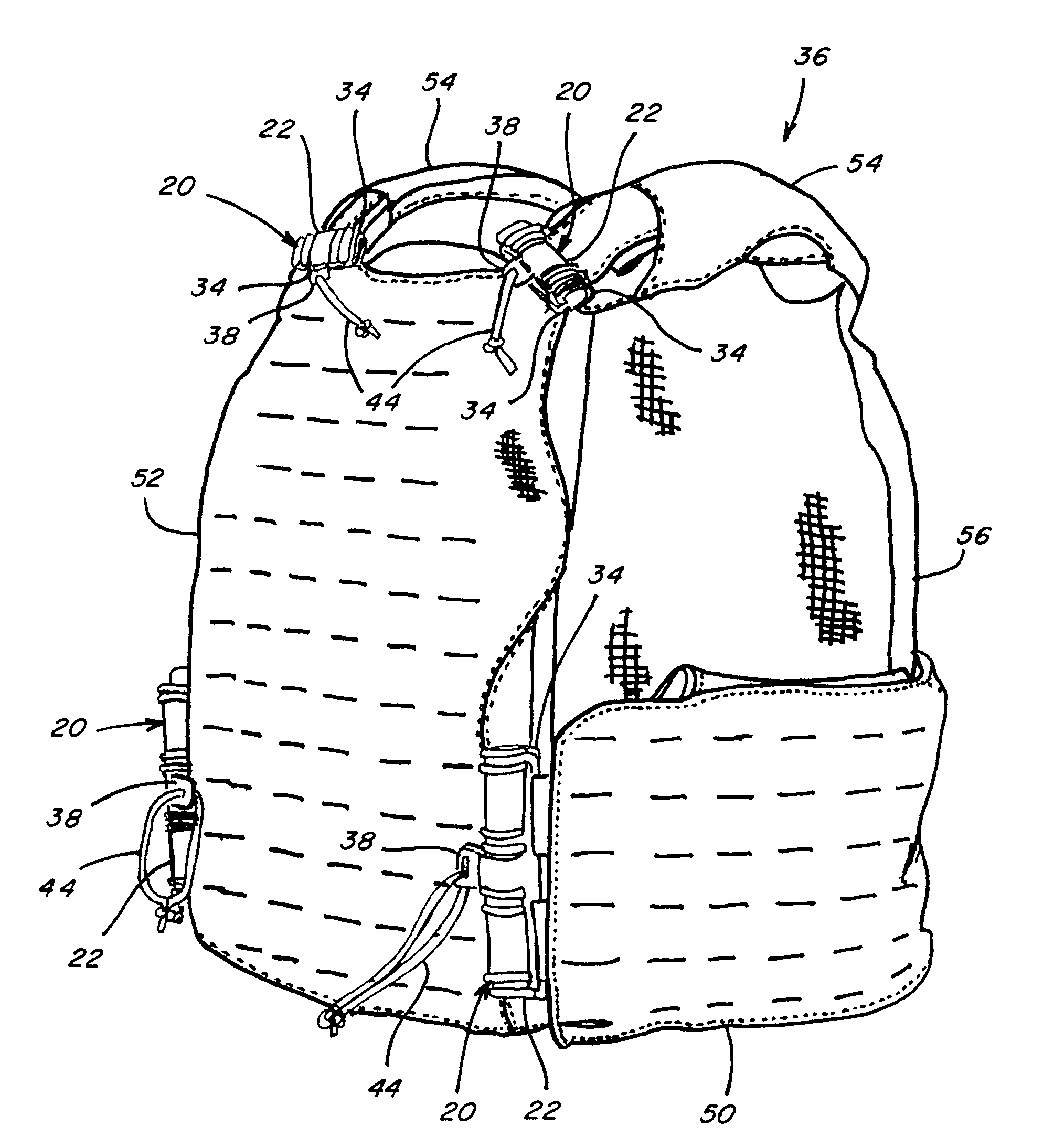
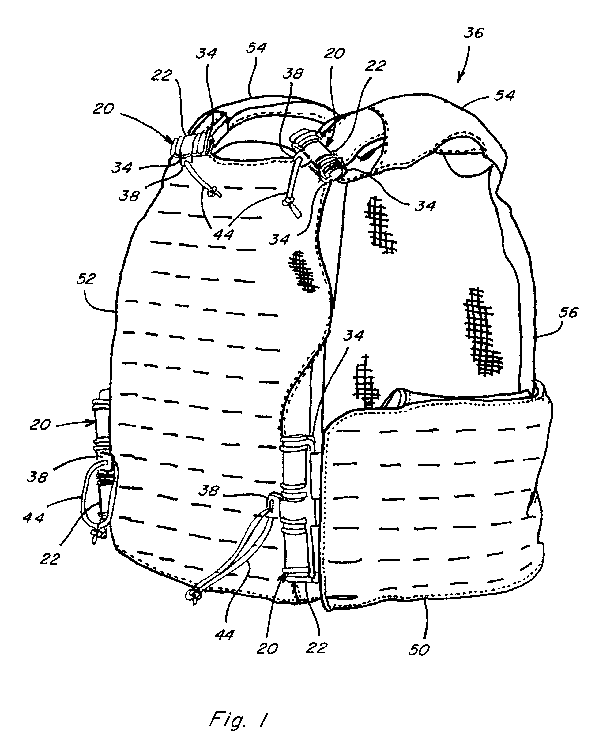
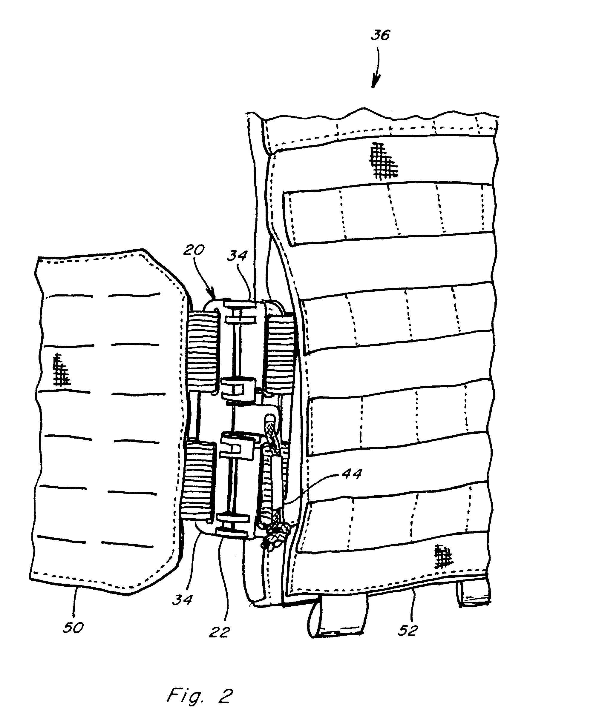
[0030]Referring to FIGS. 1 through 8, assembly and release apparatus 20 constructed and operable according to the teachings of the present invention, are shown at several location on a representative garment, which here is a ballistic vest 36, that provides a quiet and rapid manner of operation, usable for both standard donning and doffing, as well as rapid release, and which provides at least some weight advantage, and overcomes one or more of the disadvantages set forth above.

[0031]The assembly and release apparatus 20 includes a C-shape female clip 22 which is attached to a first element or location of the garment to be connected to another element or location, and an elongate male pin 24 attached to the second element or section and with relative longitudinal movement as denoted by arrow LM in FIG. 4, is cooperatively receivable in the C-shape clip 22 for connecting the garment element or sections together. As best shown in FIGS. 4-7, the C shape clip 22 extends partially circum...


PUM


Abstract

The assembly and release apparatus and method utilizes a C-shaped clip defining a channel and a smaller slot extending along the channel, both open at at least one end, attachable to a first location on a garment. A pin of the apparatus is slidably receivable in the channel through the open end to assemble the C-shaped clip and the pin together. The pin has a tab or strip that extends through the slot, for attaching the pin to a second location on the garment. The apparatus includes at least one detent element associated with one of the C-shaped clip and the pin, cooperatively engageable with the other of the C-shaped clip and the pin for retaining the pin in the channel, and releasable in a predetermined manner to allow slidably removing the pin from the channel through the open end, to provide a quiet and rapid manner of operation.

Description

[0001]This application is submitted under 35 U.S.C. 371 claiming priority to PCT / US2012 / 65854, filed Nov. 19, 2012, which application claims the benefit of U.S. Provisional Application No. 61 / 561,802, filed Nov. 18, 2011.TECHNICAL FIELD[0002]The present invention relates generally to assembly and release apparatus and method for a garment such as a ballistic vest or the like, and more particularly, which provides a quiet and rapid manner of donning and doffing the garment, so as to be usable for both standard doffing and donning, and rapid release for emergency and injury situations and the like.BACKGROUND ART[0003]U.S. Provisional Application No. 61 / 561,802, filed Nov. 18, 2011, is incorporated herein by reference in its entirety.[0004]There has long been various garments, such as, but not limited to, vests, particularly those used in tactical and military operations, such as ballistic vests including armor, that have apparatus for assembling and securely holding the garment on or ...

Claims


Application Information

Patent Timeline
Patent Type & Authority Applications(United States)
IPC IPC(8): A47G25/90A41F1/00
CPCA47G25/90A41F1/00F41H1/02A41D2300/30A41D2300/50A41D2400/44A44B11/2596Y10T24/346
Inventor BUERCK, TREVOR S.CARVER, SCOTT J.COLE, MICHAEL E.
Owner FIRSTSPEAR TUBES LLC
Why Eureka
Try Eureka