Imaging apparatus, electronic device, photostimulated luminescence detection scanner, and imaging method
a technology of luminescence detection and imaging method, applied in the field of imaging apparatus, can solve the problems of relatively expensive photomultiplier tube, and achieve the effect of improving the accuracy of photon counting
- Summary
- Abstract
- Description
- Claims
- Application Information
AI Technical Summary
Benefits of technology
Problems solved by technology
Method used
Image
Examples
first embodiment
1. First Embodiment
Example of Function Structure of Light Detection Apparatus
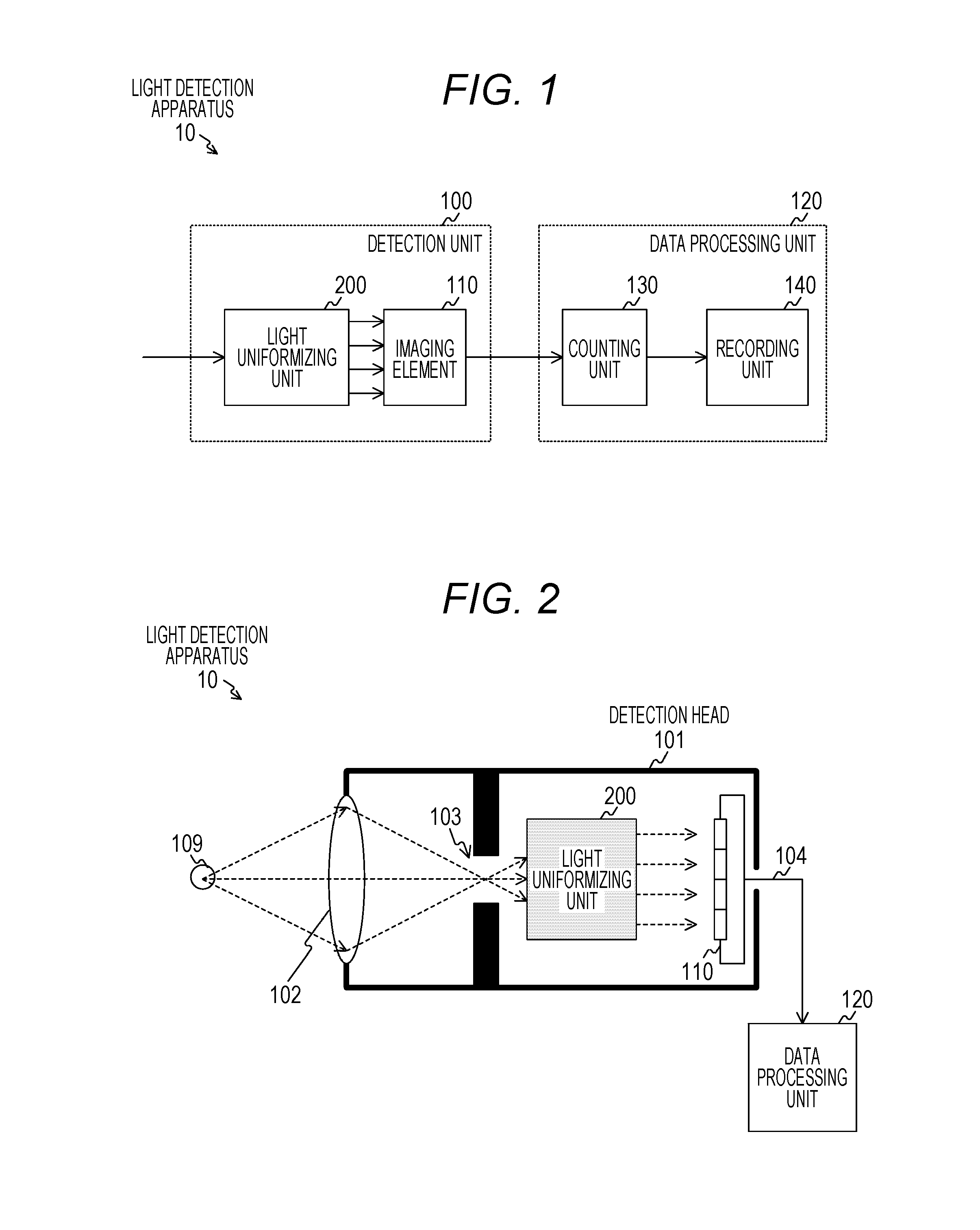
[0050]FIG. 1 is a block diagram illustrating an example of function structure related to a light detection apparatus 10 according to a first embodiment of the present technique.
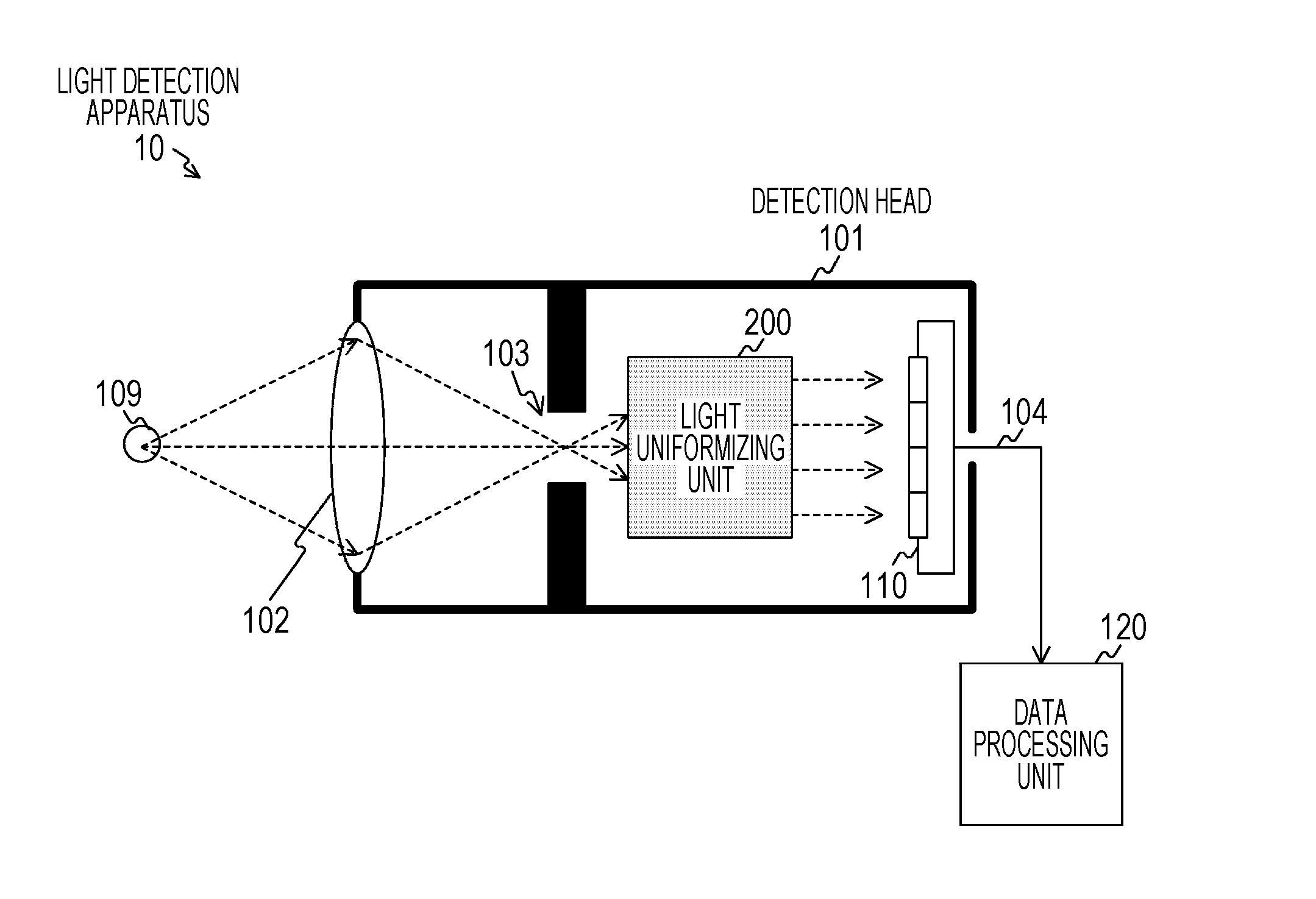
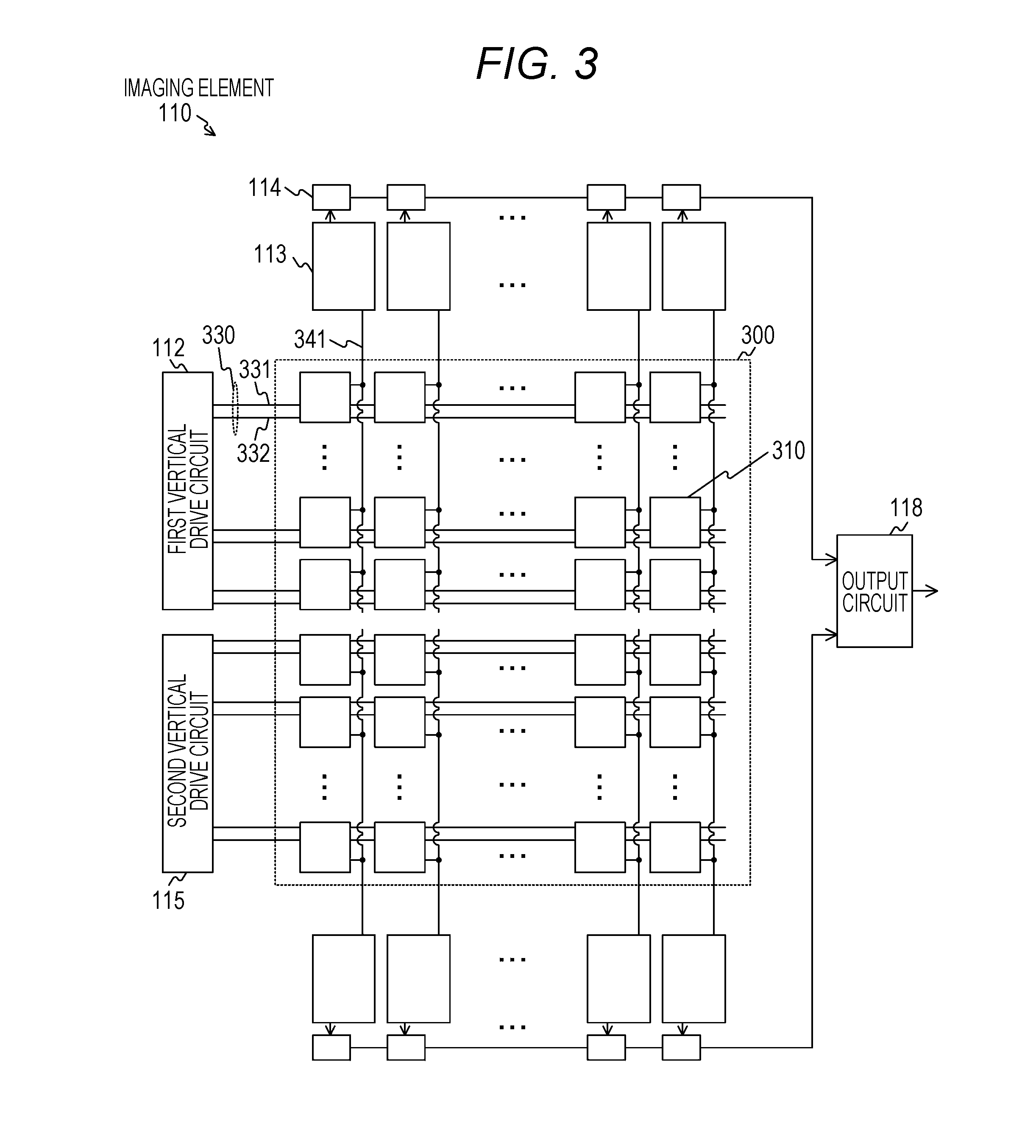
[0051]The light detection apparatus 10 is an imaging apparatus to perform photon counting by using a complementary metal oxide semiconductor (CMOS) sensor, and includes a detection unit 100 and a data processing unit 120.
[0052]The detection unit 100 converts light incident to the detection unit 100 into a digital signal, and includes a light uniformizing unit 200 and an imaging element 110.
[0053]The light uniformizing unit 200 substantially uniformizes distribution of light (light to be object of photon counting) incident to the detection unit 100, and emits, to a pixel array of the imaging element 110, the substantially uniformized light to be an object of photon counting. That is, the light uniformizing unit 200 distributes light, ...
second embodiment
2. Second Embodiment
[0188]In the first embodiment of the present technique, the description has been made on the assumption that all of the pixels in the pixel array unit is suitable for photon counting. However, actually, it is difficult to form all of the pixels in a CMOS image sensor as pixels having uniform quality. For example, a pixel having high leakage current (dark current) slightly generated even in a dark state is not suitable for photon counting.
[0189]Thus, in the second embodiment of the present technique, an example, in which count of the pixel having high dark current is made invalid (masked) to improve accuracy of photon counting, will be described with reference to FIG. 10 to FIG. 12.
[0190][Example of Relationship between Size of Dark Current and Number of Pixels]
[0191]FIG. 10 is a view schematically illustrating a relationship between the size of dark current (dark current level) generated in a pixel 310 of the second embodiment of the present technique and the num...
third embodiment
3. Third Embodiment
[0224]In the first and second embodiments of the present technique, an example, in which there is one pixel array unit including 128 lines×128 rows of pixels in an imaging element, has been described. An imaging element, which includes such a pixel array unit including small number of pixels, is quite small (for example, 2 mm square). Thus, compared to wafer working process, mounting process may become relatively expensive, in semiconductor manufacturing. Therefore, in an apparatus to which a plurality of detection apparatuses (detection head) is mounted, mounting becomes easy by lining up a plurality of pixel array units, to which a drive circuit and a readout circuit are provided, on the imaging element and by mounting them at once.
[0225]Thus, in the third embodiment of the present technique, an example, in which a plurality of pixel array units is provided on an imaging element, will be described with reference to FIG. 13 to FIG. 15.
[0226][Example of Imaging El...
PUM
 Abstract
Description
Claims
Application Information
 - R&D
- Intellectual Property
- Life Sciences
- Materials
- Tech Scout
- Unparalleled Data Quality
- Higher Quality Content
- 60% Fewer Hallucinations
Browse by: Latest US Patents, China's latest patents, Technical Efficacy Thesaurus, Application Domain, Technology Topic, Popular Technical Reports.
© 2025 PatSnap. All rights reserved.Legal|Privacy policy|Modern Slavery Act Transparency Statement|Sitemap|About US| Contact US: help@patsnap.com


