Electronic Marker Locator Systems and Methods

Active Publication Date: 2014-11-13
RADIODETECTION
View PDF6 Cites 5 Cited by
  • Summary
  • Abstract
  • Description
  • Claims
  • Application Information

AI Technical Summary

Benefits of technology

The patent describes a system that uses two antennas to calculate the depth of a target by measuring the magnetic field. The two antennas are arranged in a way that the magnetic field is measured at different locations without changing their positions. This provides more accurate depth calculations because the separation of the antennas is fixed. The system also includes a controller that prevents interference between the magnetic marker and the signals detected by the reception antennas. The technical effect of the patent is to improve the accuracy and reliability of depth measurements in various applications such as medical imaging.

Problems solved by technology

As the depth equation contains an inverse sixth power, this system is highly sensitive to errors in determining R and suffers the disadvantage of requiring the user to lift the apparatus through a predefined distance s, introducing a further source of error.

Method used


Image

  • Electronic Marker Locator Systems and Methods
  • Electronic Marker Locator Systems and Methods
  • Electronic Marker Locator Systems and Methods

Examples


Embodiment Construction

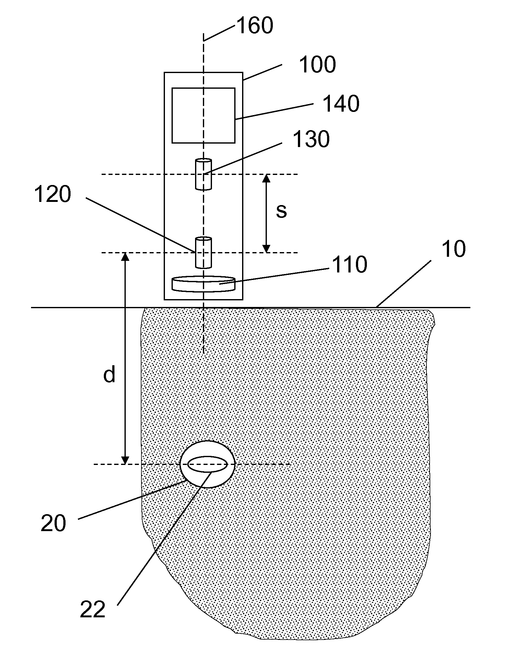
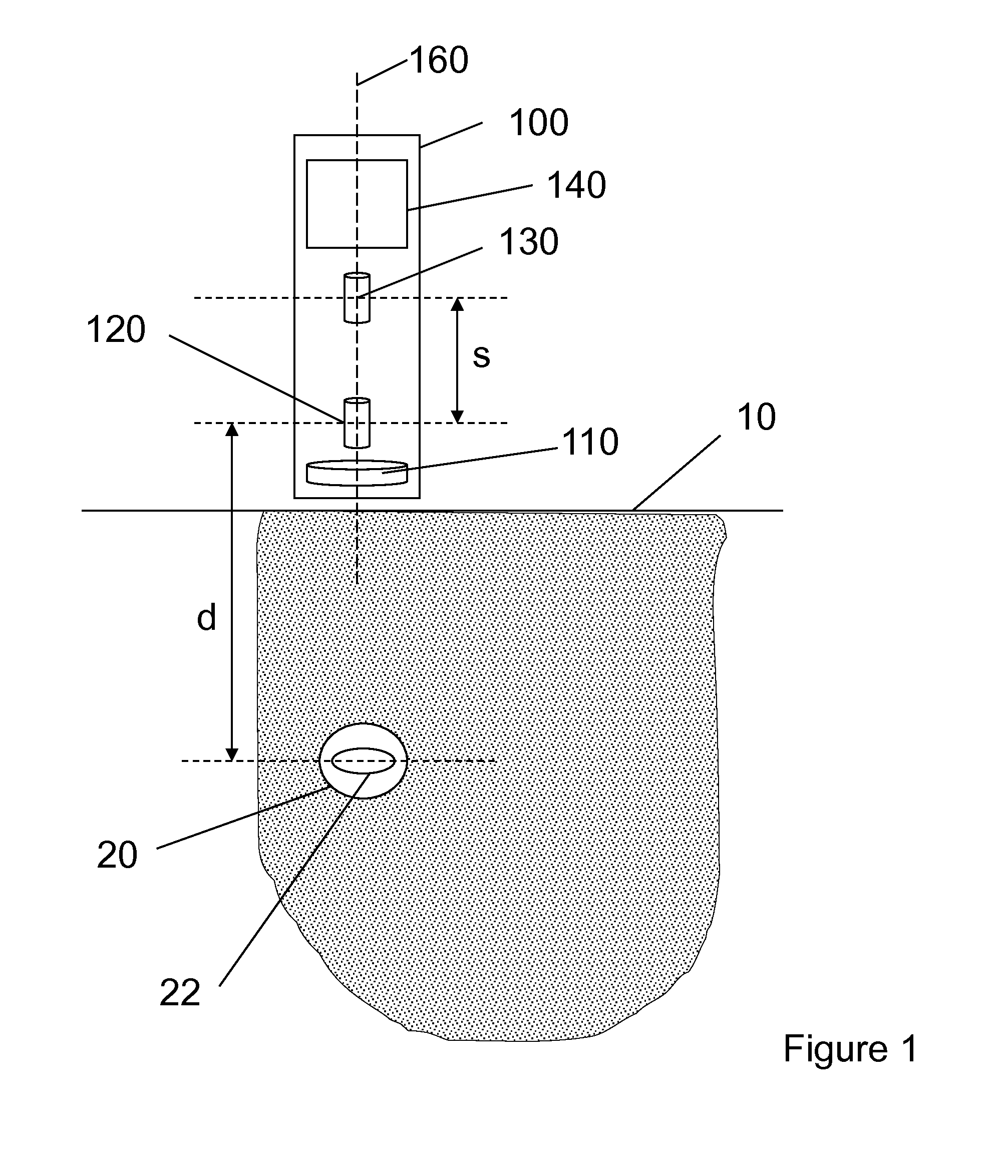
[0035]FIG. 1 shows an electronic marker locator 100 according to an embodiment. An electronic marker 20 is buried below ground level 10. The electronic marker 20 comprises a resonant circuit formed from a coil 22 and a capacitor. The electronic marker 20 has a resonant frequency, the value of which is dependent on the capacitance of the capacitor and the inductance of the coil 22.

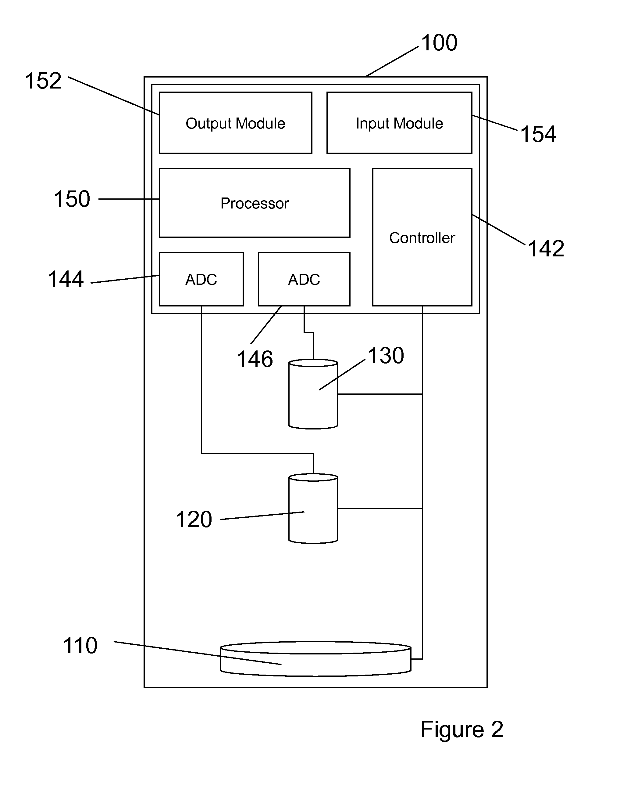
[0036]The locator 100 comprises a transmission antenna 110, a first reception antenna 120 and a second reception antenna 130. The locator 100 has control and processing module 140 which controls the antennas and processes the signals received from the antennas. The control and processing module 140 is described in more detail with reference to FIG. 2 below.

[0037]The locator 100 has a major axis 160. The transmission antenna 110, the first reception antenna 120 and the second reception antenna 130 are arranged such that their magnetic axes are parallel to the major axis 160. As shown in FIG. 1, the locator i...


PUM


Abstract

A locator for determining the depth of a buried electromagnetic marker includes a transmission antenna and two reception antennas. The locator has a major axis and is configured. The transmission antenna is configured to generate an oscillatory magnetic field parallel to the major axis. The first reception antenna of the two reception antennas is configured to couple with an oscillatory magnetic field parallel to the major axis emitted by the electromagnetic marker and to generate a first detected signal. The second reception antenna is displaced along the major axis from the first antenna and configured to couple with an oscillatory magnetic field parallel to the major axis emitted by the electromagnetic marker and to generate a second detected signal. The locator includes analogue to digital converters and a processor which is configured to calculate the depth of the electromagnetic marker.

Description

FIELD OF THE INVENTION[0001]Embodiments of the present invention relate to systems and methods for locating electronic markers. In particular, embodiments of the present invention relate to the estimation of the depth of buried electronic markers.BACKGROUND[0002]Buried electronic markers are used to indicate the location of a buried structure or utility. A buried marker is made from a circular coil that is arranged in a resonant circuit and designed to resonate at a specific frequency. An oscillatory electric current may be induced in this circuit by an externally applied pulse or pulses of magnetic flux linking the coil. The oscillatory current in the coil gives rise to an oscillatory magnetic field around the coil. The presence of this oscillatory magnetic field may be detected, allowing the position of the marker to be determined. The axis of the coil in the buried electronic marker is arranged to be oriented vertically so that the location of the buried marker may be found direc...

Claims


Application Information

Patent Timeline
IPC IPC(8): G01V3/10
CPCG01V3/10G01V3/104G01V3/15G01V15/00G01V3/00G01V3/08G01V3/081G01V3/083
Inventor PEARSON, RICHARD DAVIDTHOMPSON, JEFFREY RICHARDPOYNER, JULIAN
Owner RADIODETECTION
Why Eureka
Try Eureka