Integrated Electrical and Thermal Solution for Inverter DC-Link Capacitor Packaging

a technology of dc-link capacitors and inverter power modules, applied in the direction of electrical apparatus, cooling/ventilation/heating modifications, and modifications by conduction heat transfer, can solve the problems of increasing the size and cost of inverter power modules, and achieve the effect of reducing the temperature of capacitors and discharging hea

Active Publication Date: 2014-11-13
FORD GLOBAL TECH LLC
View PDF36 Cites 21 Cited by
  • Summary
  • Abstract
  • Description
  • Claims
  • Application Information

AI Technical Summary

Benefits of technology

[0024]An example system includes an inverter power module coupled to a capacitor package configured to dissipate heat from a bus bar through a thermally enhanced isolation layer to a case. In an example embodiment, the case can include a base and a sidewall, and the isolation layer can be disposed adjacent the case. The bus bar can be disposed adjacent the isolatio

Problems solved by technology

Unfortunately, oversized capacitors increase

Method used


Image

  • Integrated Electrical and Thermal Solution for Inverter DC-Link Capacitor Packaging
  • Integrated Electrical and Thermal Solution for Inverter DC-Link Capacitor Packaging
  • Integrated Electrical and Thermal Solution for Inverter DC-Link Capacitor Packaging

Examples


Embodiment Construction

[0033]Example embodiments of the invention are presented herein; however, the invention may be embodied in a variety of alternative forms, as will be apparent to those skilled in the art. To facilitate understanding of the invention, and provide a basis for the claims, various figures are included in the description. The figures may not be drawn to scale and related elements may be omitted so as to emphasize the novel features of the invention. Structural and functional details depicted in the figures are provided for the purpose of teaching the practice of the invention to those skilled in the art and are not to be interpreted as limitations.

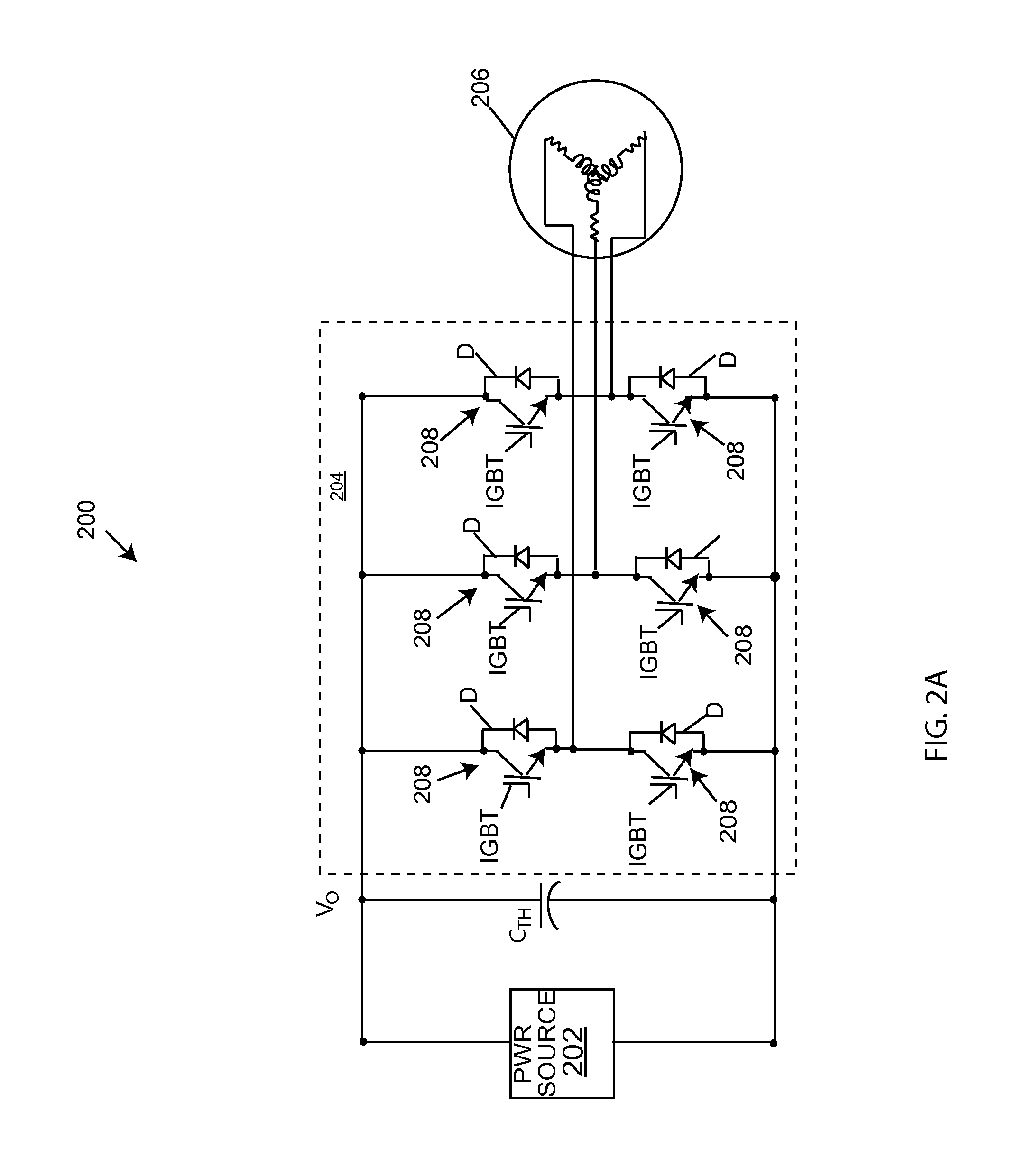
[0034]FIG. 2A shows a circuit diagram of an example system 200 of the invention. By way of example, but not limitation, the system 200 can be employed in an electric drive system of an electric or hybrid electric vehicle. A power source 202 can be coupled to an inverter 204 to drive a load 206, which, in the context of an electric vehicle, can ...


PUM


Abstract

An improved capacitor packaging solution is presented that incorporates both thermal and electrical considerations. A package can include capacitor elements electrically coupled to a bus bar, and a thermally enhanced isolation layer between the bus bar and a case. The isolation layer can be provided adjacent a case base and sidewall portions. The bus bar can be disposed adjacent the isolation layer and be configured to extend along the package side and along the package length below the capacitor elements to provide an extended path for heat dissipation from the bus bar prior to its contact with capacitor elements. The enhanced isolation layer is configured to conduct heat away from the bus bar to the case to avoid the hotspot temperature of the capacitor. Reduced capacitor temperature allows use of smaller, cheaper capacitors, reducing inverter costs without compromising performance.

Description

BACKGROUND OF INVENTION[0001]1. Field of Invention[0002]This invention relates generally to dc-link capacitors for inverter power modules, and more particularly to capacitor packaging features for electrical and thermal performance.[0003]2. Background Art[0004]Traction inverters for electric and hybrid electric vehicles typically include one or more high performance inverter circuits coupled to a power source via a passive electric device, such as a capacitor or capacitor bank that can store and release energy. The capacitor can smooth dc-link voltage, absorb ripple current, decouple power source inductance effects, and reduce the leakage inductance of the inverter power stage. To minimize parasitic or leakage inductance and optimize performance, a linking capacitor is typically positioned as close as possible to the semiconductor power switches of an inverter, with the size and design of the capacitor often driven by the size and power characteristics of the inverter to which it is...

Claims


Application Information

Patent Timeline
IPC IPC(8): H05K7/20
CPCH05K7/20509
Inventor CHEN, LIHUACHEN, CHINGCHIZAREI, SHAHRAM
Owner FORD GLOBAL TECH LLC
Why Eureka
Try Eureka