
Rotational-angle detection device and electric power-steering device provided with rotational-angle detection device

a detection device and detection device technology, applied in the direction of compasses, non-deflectable wheel steering, underwater vessels, etc., can solve the problems of motor not being appropriately driven, shaft misalignment cannot be addressed, detection error can be cancelled, etc., to reduce the amplitude of the physical amount generated and reduce the amplitude of the physical amoun

Active Publication Date: 2014-11-13
TOYOTA JIDOSHA KK
View PDF4 Cites 132 Cited by
  • Summary
  • Abstract
  • Description
  • Claims
  • Application Information

AI Technical Summary

Benefits of technology

The present invention is related to a device that detects the rotational angle of a rotating shaft and adjusts the angle to reduce detection errors caused by misalignment. When misalignment is detected, the device stops the steering assist to increase safety and notify the driver of the abnormality. This invention improves the accuracy and reliability of detecting the angle of a rotating shaft.

Problems solved by technology

However, the rotational-angle detection device proposed by Patent Literature 1 cancels the detection error caused by the shaft misalignment by simply using the two MR sensors, and does not actually detect the occurrence of the shaft misalignment.
Moreover, the detection error can be cancelled only when the shaft misalignment occurs in a specific direction.
Therefore, even when a large shaft misalignment occurs, and the detection error cannot be cancelled, the detection value of the rotational angle is directly used.
As a result, when the detection accuracy of the rotational angle is decreased by the shaft misalignment, the motor cannot be appropriately driven, and a countermeasure such as changing a control form of the motor drive becomes necessary in terms of the motor control.
However, the rotational-angle detection device proposed by Patent Literature 1 cannot detect the shaft misalignment, and the shaft misalignment cannot be addressed.
Moreover, when one MR sensor fails even in a state where the detection error caused by the shaft misalignment of the rotary shaft can be cancelled by the two MR sensors, the detection error cannot be subsequently cancelled.
Thus, the shaft misalignment cannot be addressed in this case either.

Method used

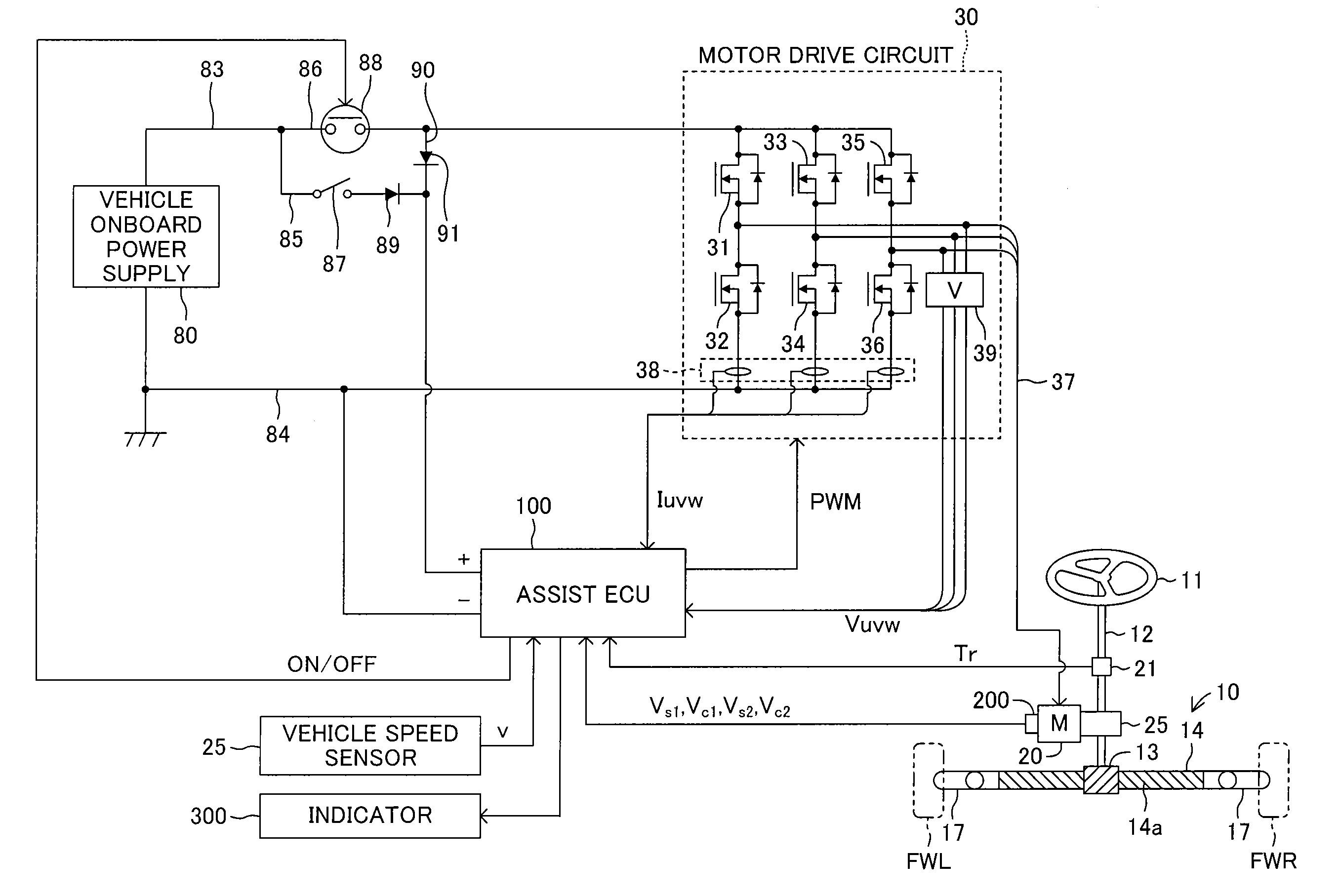
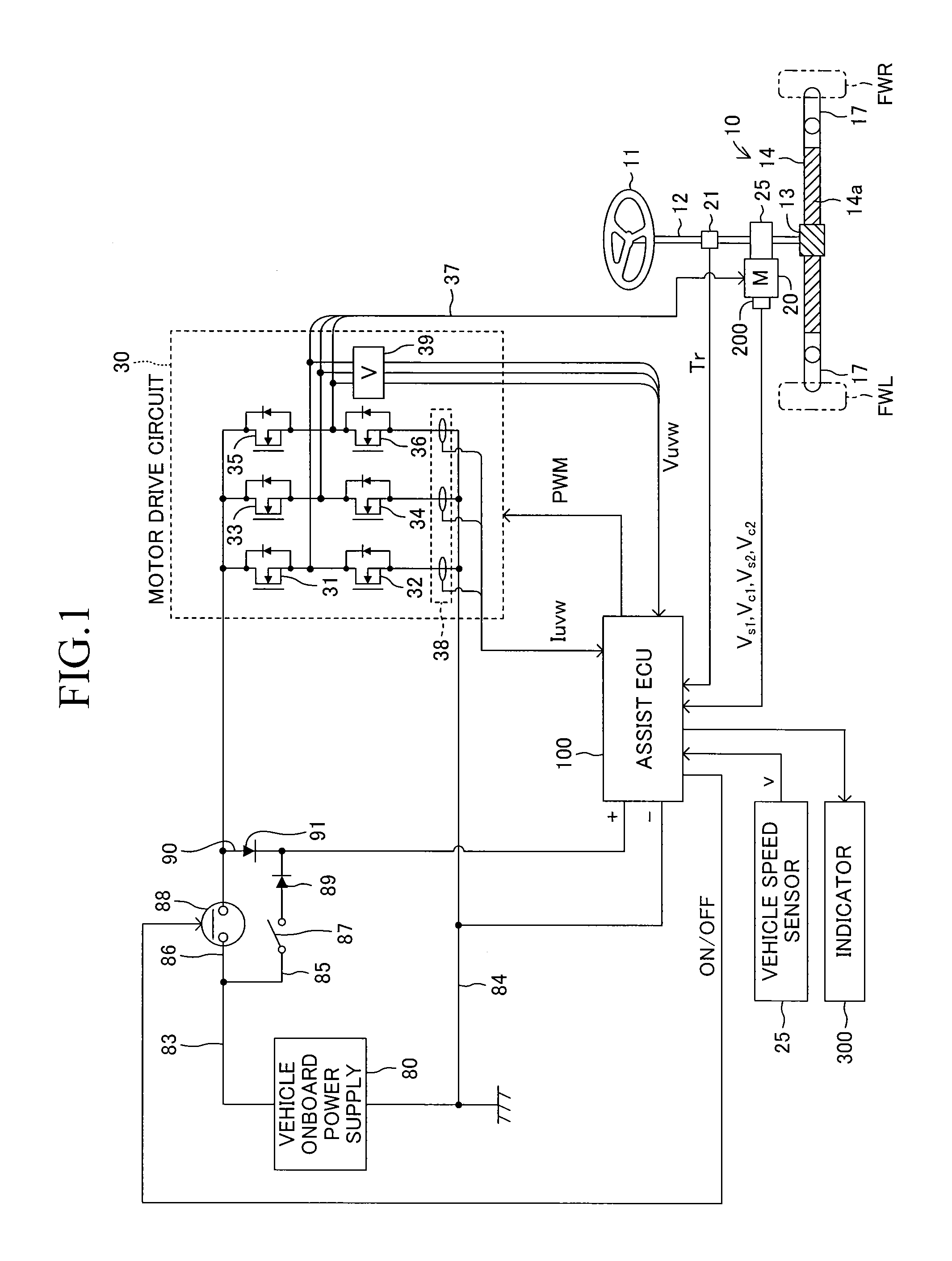
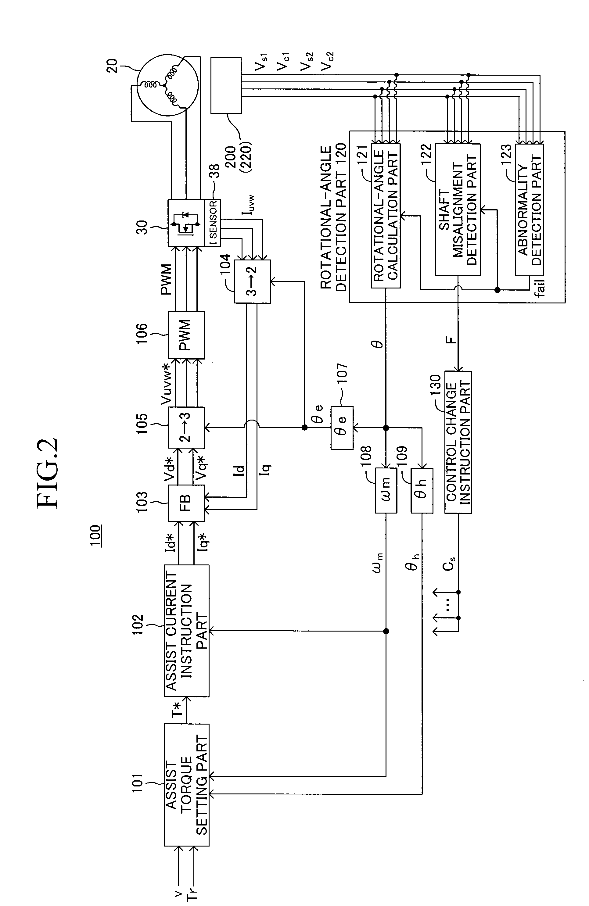

Image

  • Rotational-angle detection device and electric power-steering device provided with rotational-angle detection device
  • Rotational-angle detection device and electric power-steering device provided with rotational-angle detection device
  • Rotational-angle detection device and electric power-steering device provided with rotational-angle detection device

Examples


second embodiment

[0179]The correction part 124 inputs the motor rotational angle calculated by the rotational-angle calculation part 121, inputs the shaft misalignment determination flag F output from the shaft misalignment detection part 122, simply outputs, when the shaft misalignment determination flag F is “0”, the motor rotational angle input from the rotational-angle calculation part 121, and outputs, when the shaft misalignment determination flag F is “1”, a motor rotational angle corrected so as to reduce the influence of the shaft misalignment as the final motor rotational angle θ. In the following, in the second embodiment, the motor rotational angle calculated by the rotational-angle calculation part 121 is referred to as motor rotational angle θ′, and the rotational angle calculated by the correction part 124 is referred to as motor rotational angle θ in order to distinguish the motor rotational angle calculated by the rotational-angle calculation part121 and the motor rotational angle c...

first embodiment

[0217]The control change instruction part 1301 inputs the shaft misalignment determination flag F output from the shaft misalignment detection part 122, and outputs an instruction signal Ct for specifying the calculation method for a target assist torque T* to the assist torque setting part 1011 depending on the shaft misalignment determination flag F. The shaft misalignment determination flag F is directly used as the instruction signal Ct. FIG. 25 illustrates processing by the assist torque setting part 1011 in a part different from the processing by the assist torque setting part 101 according to the In Step S81, the assist torque setting part 1011 reads the instruction signal Ct representing the shaft misalignment determination flag F, determines whether the shaft misalignment determination flag F is “1” or not, and, when the shaft misalignment determination flag F is “1”, namely, the occurrence of the shaft misalignment is detected, in Step S82, sets the dumping compensation t...

third embodiment

[0231]A description is now given of the present invention. The third embodiment is configured so as to switch the control form of the steering assist in three ways based on the shaft misalignment degree Q. In the following, like components as those of the second embodiment are denoted by like symbols as those of the second embodiment in drawings, and a description thereof is omitted.

[0232]FIG. 28 is a functional block diagram illustrating processing by the microcomputer of the assist ECU 100 according to the third embodiment. The assist ECU 100 according to the third embodiment includes an electrical angle estimation part 140 and an electrical angle selection part 150 in addition to the configuration of the second embodiment. Moreover, the assist ECU 100 includes, in place of the angular velocity calculation part 108, the steering angle calculation part 109, and the control change instruction part 1301 according to the second embodiment, an angular velocity calculation part 1081, a ...


PUM


Abstract

When a shaft misalignment detection part detects occurrence of a shaft misalignment that is a misalignment in a relative position in a radial direction of a rotary shaft between a magnet part and a sensor part, the shaft misalignment detection part outputs a shaft misalignment determination flag to a correction part and a control change instruction part. The correction part calculates a motor rotational angle so as to reduce a detection error caused by the shaft misalignment. The control change instruction part outputs instructions of changing calculation methods so that influence by the detection error decreases to an assist torque setting part and an assist current instruction part.

Description

TECHNICAL FIELD[0001]The present invention relates to a rotational-angle detection device for detecting a rotational angle of a rotary shaft of a motor, and the like, and to an electric power-steering device, using the rotational-angle detection device, for detecting a rotational angle of a motor and controlling drive of the motor based on the detected rotational angle, to thereby generate a steering assist torque.BACKGROUND ART[0002]In the related-art, a rotational-angle detection device for detecting a rotational angle of a rotary shaft by means of a magnetic sensor is known. For example, Patent Literature 1 proposes a rotational-angle detection device including a magnetic member fixed to a rotary shaft and magnetized as an N pole and an S pole at predetermined intervals in a peripheral direction of the rotary shaft, and a sensor part including two MR sensors arranged so as to oppose the magnetic member to detect a change in a magnetic field caused by the N pole and the S pole at ...

Claims


Application Information

Patent Timeline
Patent Type & Authority Applications(United States)
IPC IPC(8): B62D5/04G01B7/30
CPCB62D5/0481B62D5/0463G01B7/30G01D5/145G01D3/02G01B7/31
Inventor YANAI, KOHEIAOKI, KENICHIRO
Owner TOYOTA JIDOSHA KK
Learn More