Dual-Clutch Transmission

a transmission and clutch technology, applied in mechanical equipment, transportation and packaging, gearing, etc., can solve the problems of cost saving and particularly achieve the effects of small installation space requirements, good hybridization capability, and good powershift capability results

Active Publication Date: 2014-11-20
ZF FRIEDRICHSHAFEN AG
View PDF11 Cites 5 Cited by
  • Summary
  • Abstract
  • Description
  • Claims
  • Application Information

AI Technical Summary

Benefits of technology

[0007]According to the invention, the dual clutch transmission comprises only six gear planes with at least nine assigned gear ratio steps which can be realized via only four double shift elements and at least one single shift element. In order to realize a particularly compact dual clutch transmission, preferably four gear ratio steps can be coupled with each countershaft via double shift elements, and one of the transmission input shafts can be coupled with a gear ratio step via a single shift element. In this way, at least nine speeds are realized in the dual clutch transmission according to the invention without twofold use of gear ratio steps, i.e., winding gears. In addition, a very good powershift capability results and, if required, a good hybridization capability.
[0008]A further advantage results in the present dual clutch transmission in that only five actuators are required for actuating the provided shift elements. On the one hand, this results in a particularly small installation space requirement and also in cost savings due to the small quantity of required actuators.
[0009]In a particularly advantageous manner, the dual clutch transmission according to the invention can be converted in an identically functioning manner by different positioning of the gear planes and spur gear steps or gearwheel steps assigned to the gear planes and / or of the shift elements or synchronizers when the assignment of the individual shift elements to the spur gear steps or gear ratio steps is retained. In this way, the respective shift matrix or shift scheme for the resulting gear set variants is not changed even when the arrangement of the gear ratio steps or shift elements is changed.

Problems solved by technology

On the one hand, this results in a particularly small installation space requirement and also in cost savings due to the small quantity of required actuators.

Method used


Image

  • Dual-Clutch Transmission
  • Dual-Clutch Transmission
  • Dual-Clutch Transmission

Examples


Embodiment Construction

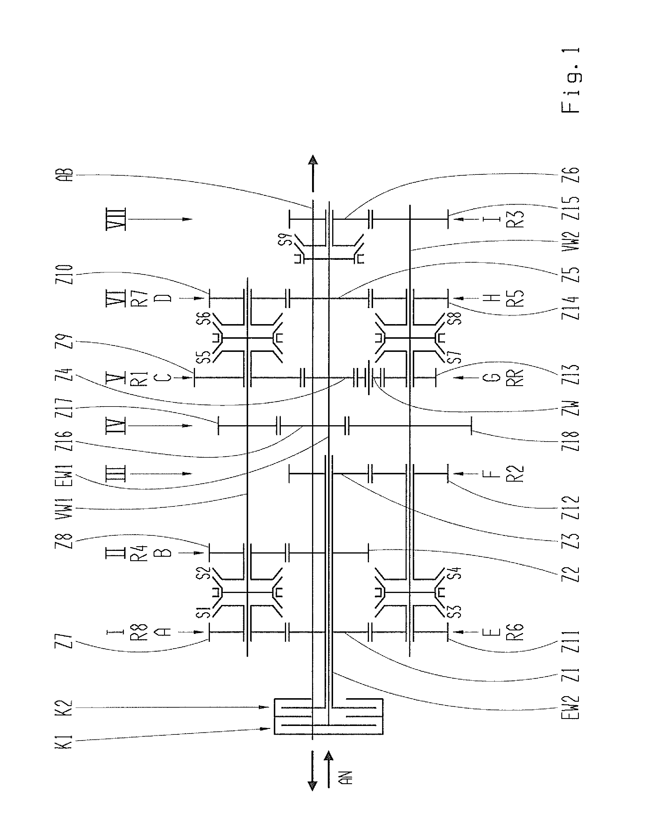
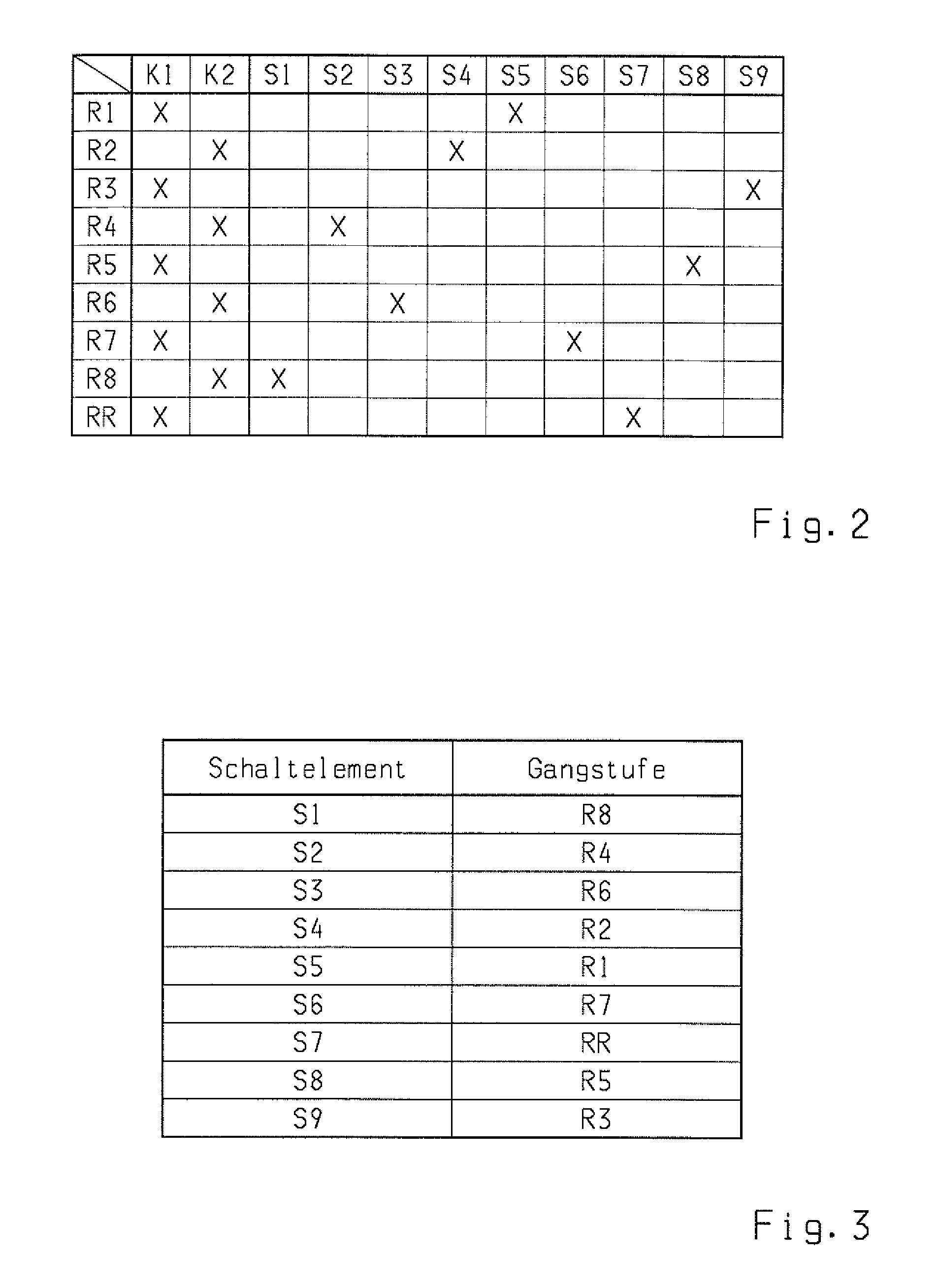
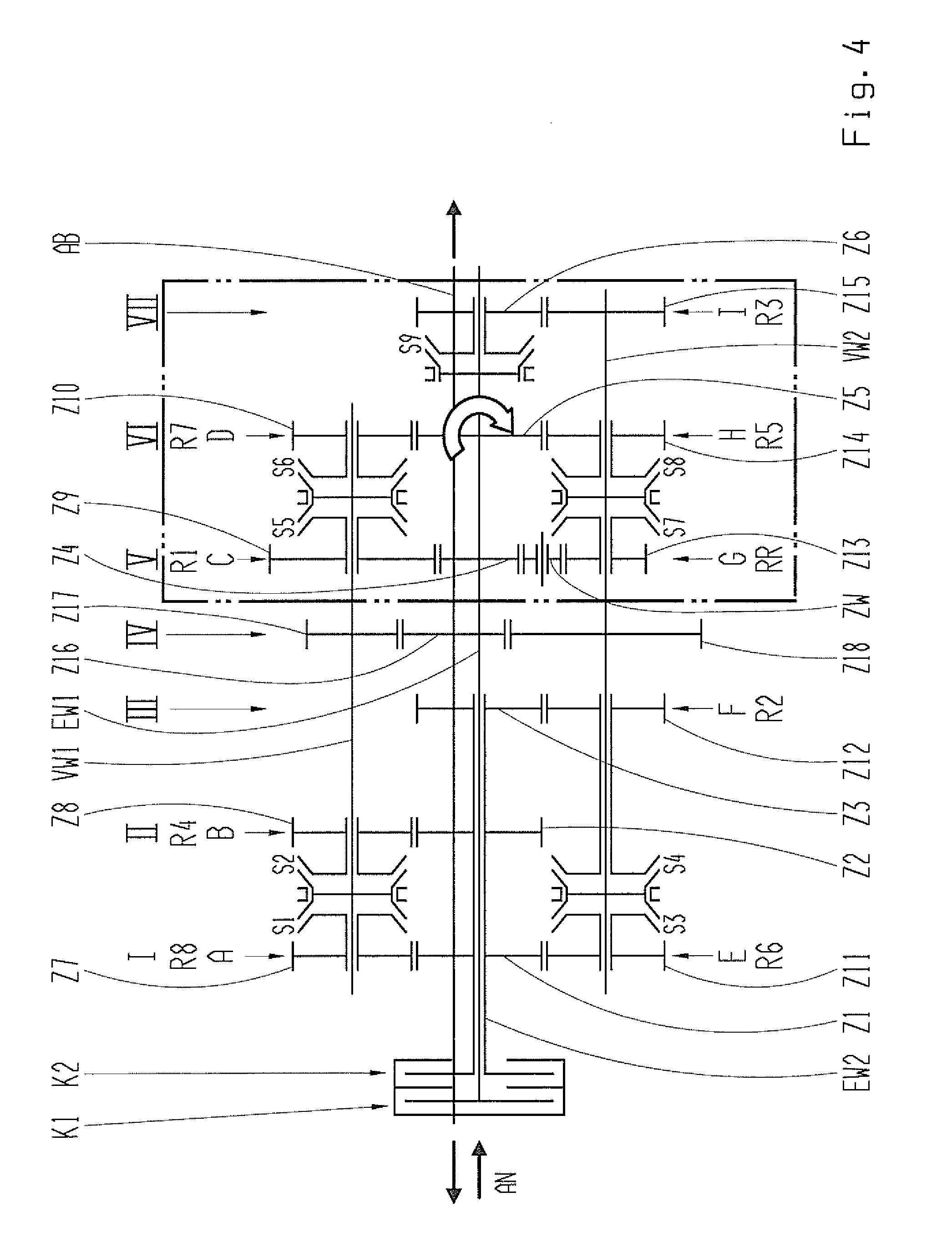
[0026]Various constructional variants of a dual clutch transmission according to the invention are shown by way of example in the drawings. The countershaft-type dual clutch transmission for a vehicle comprises a dual clutch with a first clutch K1 and a second clutch K2 having input sides connected to a driveshaft AN and having output sides connected respectively to one of two transmission input shafts EW1, EW2 arranged coaxial to a mainshaft axis. The first transmission input shaft EW1 which is connected to the first clutch K1 is constructed a solid shaft, and the second transmission input shaft EW2 which is connected to the second clutch K2 is constructed as a hollow shaft.

[0027]The first sub-transmission is assigned to the first transmission input shaft EW1, and two fixed gears Z4, Z5 arranged coaxial to the mainshaft axis and an idler gear Z6 arranged coaxial to the mainshaft axis are provided at the first transmission input shaft EW1. The second sub-transmission is assigned to ...


PUM


Abstract

A countershaft-type dual clutch transmission for a vehicle has two clutches having input sides connected to a driveshaft (AN) and output sides connected respectively to one of two transmission input shafts arranged coaxial to a mainshaft axis. A sub-transmission is associated in each instance with the transmission input shafts, at least two countershafts, a plurality of gear planes to which are assigned gear ratio steps, and at least one output shaft which can be connected to the sub-transmissions via an output gear plane. Only six gear planes with at least nine assigned gear ratio steps can be realized via only four double shift elements and at least one single shift element. Each countershaft can be coupled with four gear ratio steps via double shift elements, and one of the transmission input shafts can be coupled with a gear ratio step via a single shift element.

Description

BACKGROUND OF THE INVENTION[0001]1. Field of the Invention[0002]The present invention is directed to a dual clutch transmission for a vehicle.[0003]2. Description of the Related Art[0004]U.S. Pat. No. 8,365,623 and U.S. Pat. No. 8,393,238 disclose a dual clutch transmission with two clutches having input sides connected to a driveshaft, while the output sides of the clutches are connected, respectively, to one of two transmission input shafts which are arranged coaxial to one another. Further, two countershafts are provided which are arranged axially parallel to one another. Three idler gears engaging with fixed gears of the transmission input shafts are associated with the countershafts in each instance. Six shift elements or coupling devices are required to shift the idler gears of the countershafts. In addition, a further shift element is provided for connecting two idler gears of a countershaft to one another. In total, at least three gear planes and one output gear plane are re...

Claims


Application Information

Patent Timeline
Patent Type & Authority Applications(United States)
IPC IPC(8): F16H3/093B60K6/547
CPCF16H3/093Y10S903/902B60K6/547F16H3/006F16H2200/006F16H2003/0931F16H2003/0933B60K2006/4816Y02T10/62Y10T74/19014Y10T74/19228
Inventor MICHEL, CHRISTIANWAFZIG, JURGENWECHS, MICHAELRENNINGER, MARKUSROSEMEIER, THOMASKALTENBACH, JOHANNES
Owner ZF FRIEDRICHSHAFEN AG
Why Eureka
Try Eureka