Method of Single Line Mooring

a single-line mooring and mooring technology, applied in special-purpose vessels, vessel construction, transportation and packaging, etc., can solve the problems of affecting operation, all three options are potentially bad,

Active Publication Date: 2014-11-20
REEL POWER LICENSING
View PDF11 Cites 31 Cited by
  • Summary
  • Abstract
  • Description
  • Claims
  • Application Information

AI Technical Summary

Benefits of technology

[0006]A second object of this invention is to provide passive means to control the watch circle.

Problems solved by technology

All three options are potentially bad.
Dense spacing and large watch circles would mean that they would tangle with one another and interfere with the operations.

Method used


Image

  • Method of Single Line Mooring
  • Method of Single Line Mooring
  • Method of Single Line Mooring

Examples


Embodiment Construction

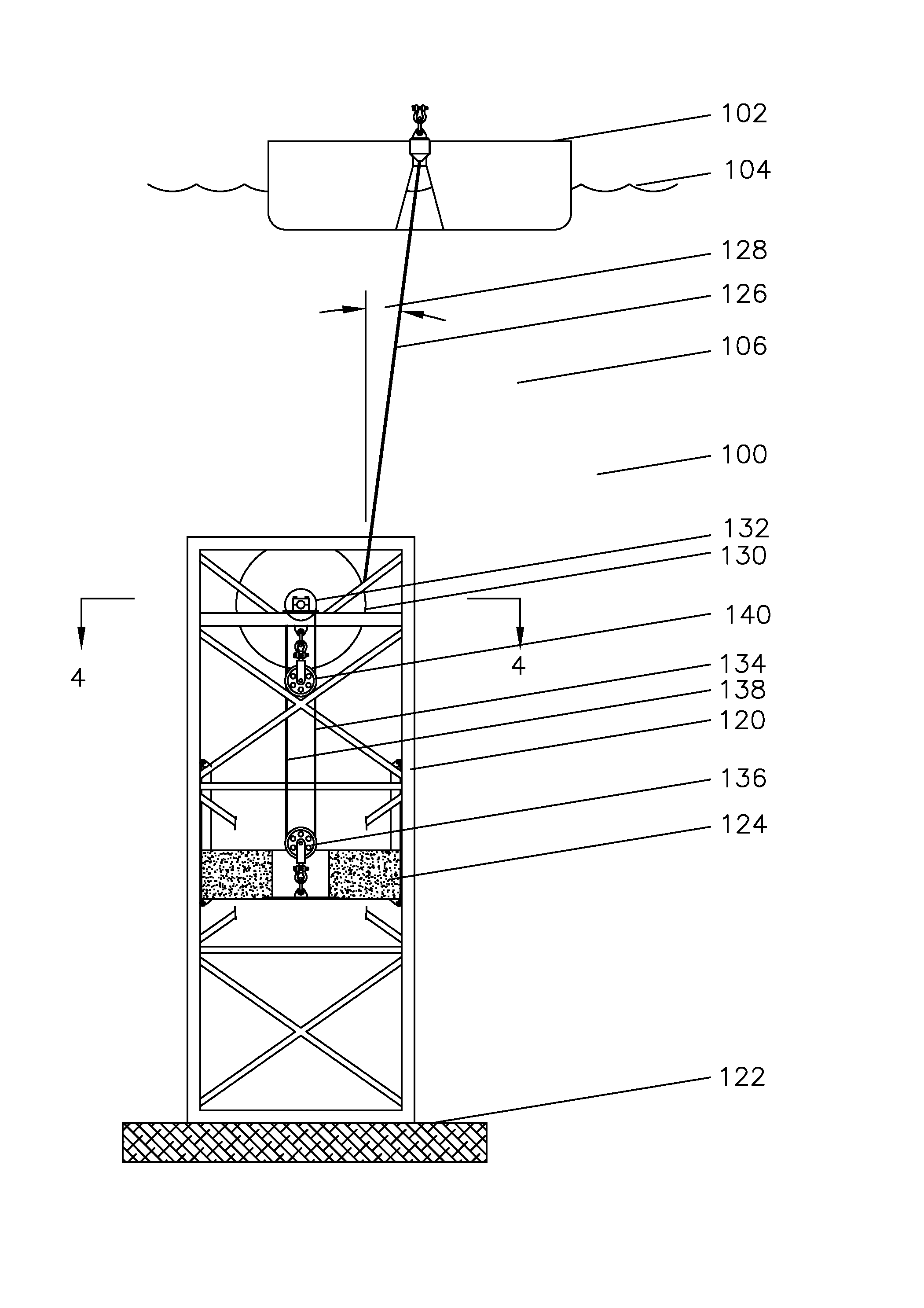
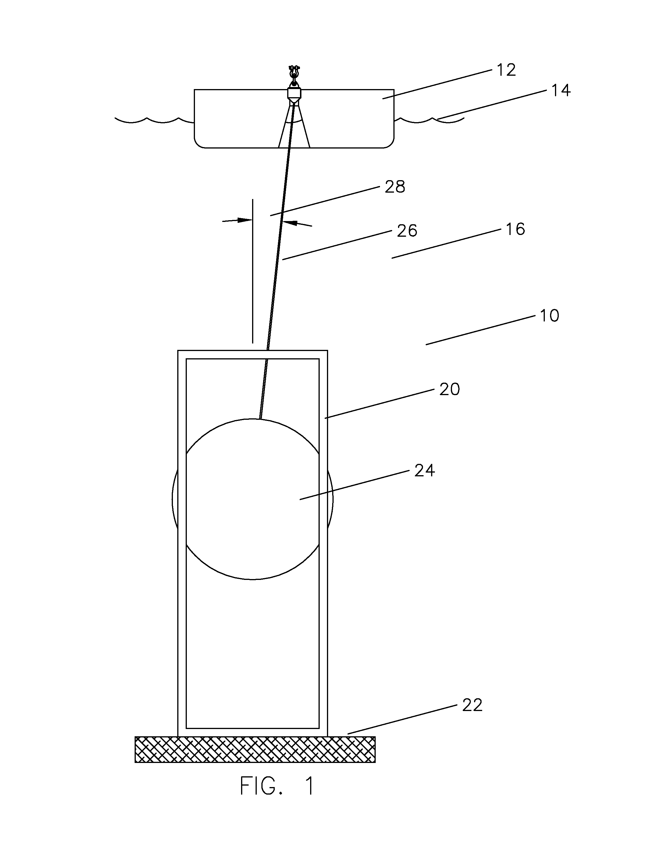
[0015]Referring now to FIG. 1, a view of a complete system for the single line mooring system 10 is shown with vessel 12 at the surface 14 of the body of water 16. Mooring structure 20 is landed on the floor 22 of the body of water and contains a weight 24 with a line 26 up to vessel 12. Line 26 is shown at angle 28 from vertical which would be variable based upon water currents and wind speeds. Angle 28 will be constant for a fixed or maximum water current and wind speed. In this figure, weight 24 simply moves up and down within mooring structure 20 with a constant line length and so the water working depth range of the system as shown would be generally the height of the mooring tower 20.

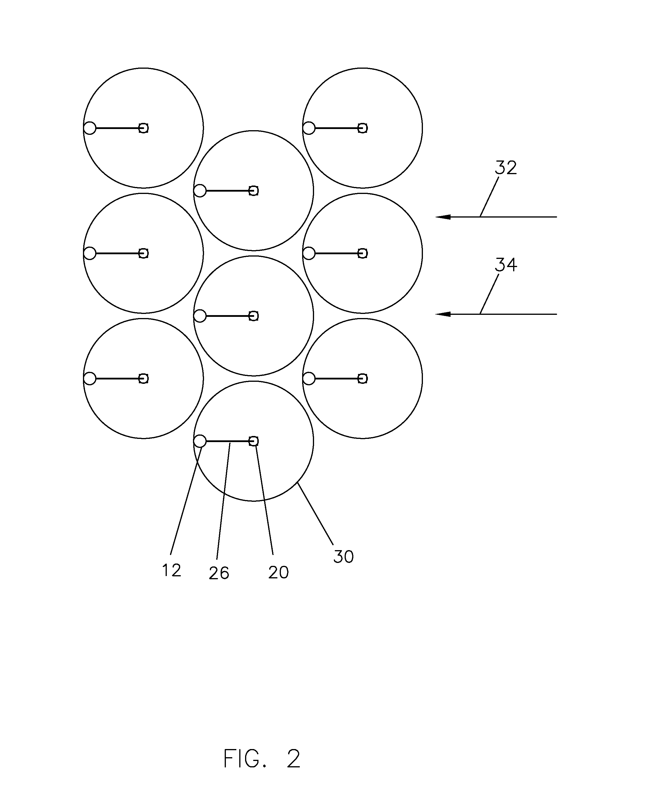
[0016]Referring now to FIG. 2 which is a vertical view of what is shown in in FIG. 1 shown several times, watch circle 30 is shown around several vessels 12 which are shown at maximum current 32 and maximum winds speed 34. At these maximum conditions, the diameter of watch circle 30 is of a maximu...


PUM


Abstract

The method of mooring buoyant equipment at the surface of a body of water in a controlled position using a single line by connecting a first line from the buoyant equipment to a first diameter drum on a subsea mooring tower, connecting the first diameter drum to a second diameter drum, connecting a second line from the second diameter drum to a weight, such that when the depth of the body of water changes the tension on the first line remains the same and the vertical distance travelled by the weight is less than the change in the depth of the body of water.

Description

TECHNICAL FIELD[0001]This invention relates to the method of using a single line to moor a vessel within a tight watch circle in a body of water of varying depth.BACKGROUND OF THE INVENTION[0002]Conventional mooring of a vessel using a single line generally involves dropping an anchor and letting the vessel weathervane to the downstream position from the anchor point. The variability of the depth must be considered in the amount of anchor line which if deployed. Consider, for example, water level varies between 100 foot depth and 400 foot depth and the anchor is set tightly when the water is at a depth of 100 feet. When the water depth moves towards 400 feet, the anchor line will either hold the vessel down until it sinks, the anchor line will be broken, or the anchor will be pulled out of the floor below the body of water. All three options are potentially bad.[0003]Such a variability of depth occurs in situations such as sanitation ponds where the water level varies substantially ...

Claims


Application Information

Patent Timeline
Patent Type & Authority Applications(United States)
IPC IPC(8): B63B21/50
CPCB63B21/50B63B21/29B63B21/46B63B21/502B63B21/00B63B2021/003B63B2021/206B63B2021/225B63B22/04B63B22/18B63B22/20
Inventor BAUGH, BENTON FREDERICKSPENCE, MICHAEL LEROY
Owner REEL POWER LICENSING
Why Eureka
Try Eureka