
Open Energy System

a technology of energy system and solar energy, applied in the field of power system, can solve the problems of many being heavy in weight, unable to obtain electric power, and unable to get electricity where, so as to enhance the convenience of mobility of solar electric power units, improve the deployment and containment of mobile power units, and facilitate the operation of units

Active Publication Date: 2014-11-20
CASTER CASSANDRA ARINA +1
View PDF15 Cites 12 Cited by
  • Summary
  • Abstract
  • Description
  • Claims
  • Application Information

AI Technical Summary

Benefits of technology

The present invention is about a self-contained solar electric power generating unit. It has several benefits. Firstly, it improves the deployment and containment of mobile power units. Secondly, it enhances the convenience of mobility of solar electric power units by allowing for multiple ways to transport the unit. Thirdly, it can be operated by one person using limited to no equipment and otherwise operate the unit with ease, even to an individual with little to no experience in solar generating units. Fourthly, it provides alternative and clean sources of power by reducing human exposure to harmful and dangerous fuels. Fifthly, it allows for such clean, alternative electric power in locations where there is no grid connectivity.

Problems solved by technology

Getting electricity where and when it is needed is an issue faced around the world.
While many locations may have readily available access to traditional electrical power grids, there remain vast regions where electric power is not obtainable.
Further, while there are portable, self-contained electric power units available on the market today, many are heavy in weight, not easily maneuverable, have small output and are difficult to assemble.
Knowledge of electrical assembly, heavy lifting and tedious logistics become necessary to operate such existing devices.
In turn, disassembly also becomes a contending issue.
Units that are not self-contained are more or less permanently attached to a structure making removal near impossible if not improbable.
Many units are not pre-wired or pre-assembled and are otherwise not ready to use upon delivery.
ISO shipping containers are also very large and have many transportation limitations.
Additionally, mobility is an issue for remote power systems.
Generally many units are not designed for efficient transportation once the destination has been reached.
Units must be disassembled and moved with a fork lift or other heavy equipment each time or in some cases the unit cannot be moved once it is placed, due to its weight.
This method is limited by its weight and size.
Whereas transportability may be achieved, mobility is restricted.
The ability for an individual(s) to assemble and disassemble may also be an obstacle.
This unit is limited in its ability to be transportable as it is not self- contained.
Delivery of the unit has also previously been cumbersome and requires heavy equipment.
Long distances for overseas haul are further limited as the unit cannot be easily placed inside shipping containers as the array mast is protruding.
Disassembly would be the only solution for this design which would further negate the simplicity and ready to use nature of the unit.
This design is limited in the number of modules it can hold and thus the amount of wattage the system produces.
Additionally, the solar panels must be manually secured in place with a lock in pin, adding to assembly and creating more objects and pieces that can become lost through transportation and assembly / disassembly.
The unit however is not easily transportable overseas or for any other form of transportation other than being pulled behind a vehicle that is able to pull it.
The unit is also not self-contained and is restricted by weight and due to the nature of the design, is always open and subject to environmental factors unless it is completely disassembled.
Existing power generating units also lack versatility in utilizing other types of sources to generate power.
Utilization of many types of power can be difficult and even dangerous.

Method used


Image

  • Open Energy System
  • Open Energy System
  • Open Energy System

Examples


Embodiment Construction

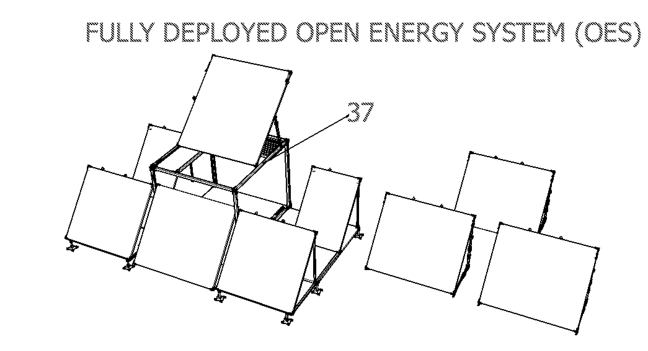
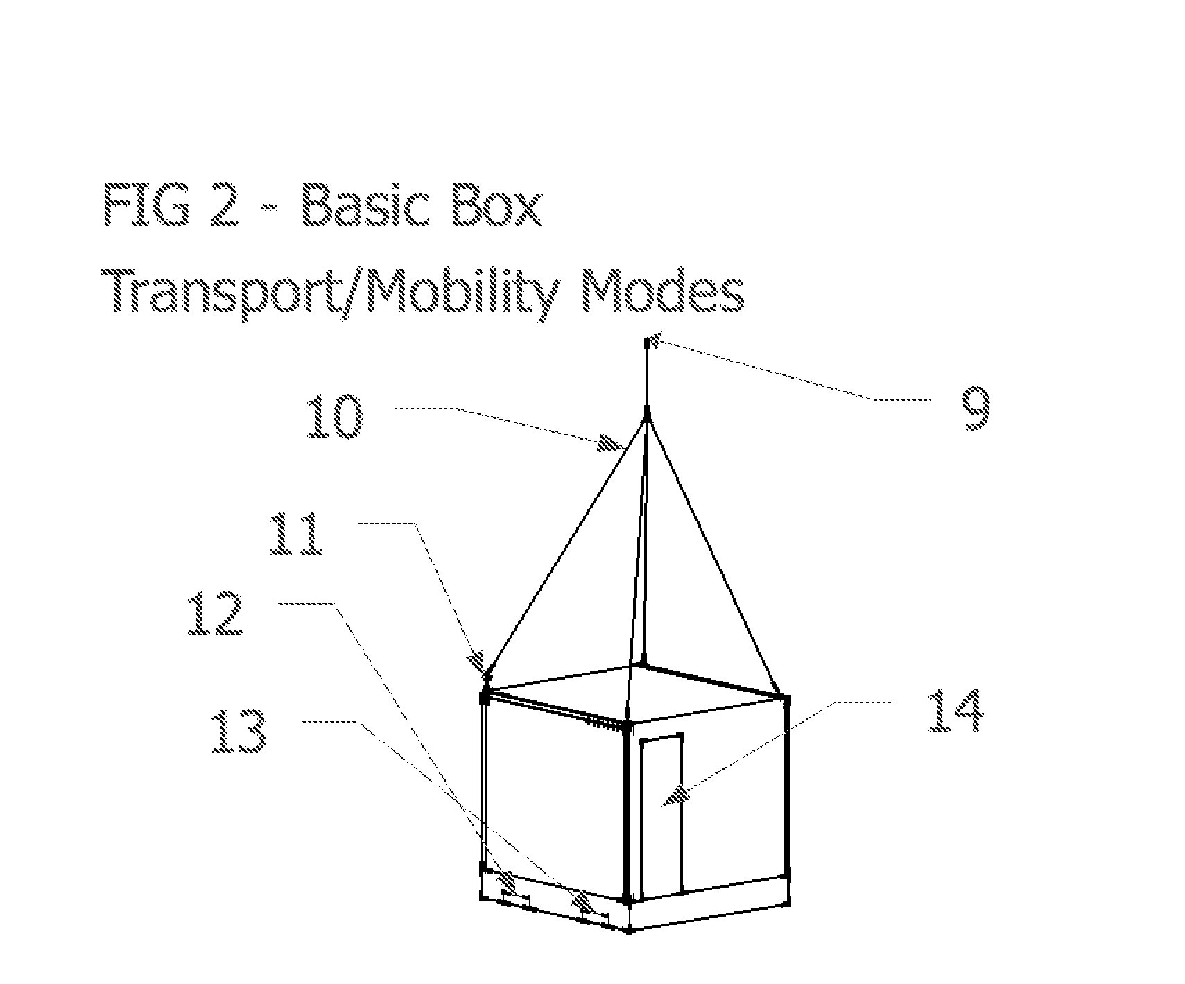
[0040]FIG. 2 and FIG. 8 show sectional views of the best mode contemplated by the inventor of the portable and preassembled renewable electrical power generating unit according to the concepts of the present invention. FIG. 1-FIG. 8 are presented and described below. However, FIG. 2 and FIG. 8 demonstrate the present invention fully deployed and completely closed to best understand the entirety of the concept.[0041]2. How to Make the Invention

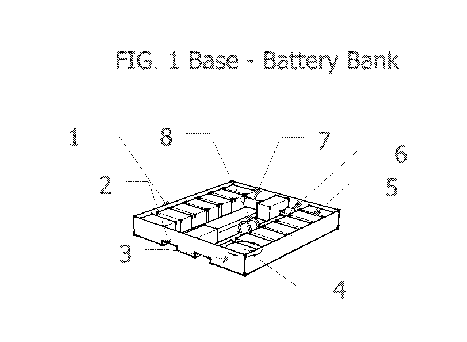
[0042]As can be amply seen from the drawings the Open Energy System (OES), is a portable and preassembled hybrid renewable electrical power generating unit that is self-contained, mobile and relevant to the portable energy field. As shown in FIG. 1 the OES sits atop a skid base 1 that is hollowed to house the electrical components of the present invention. The base of the unit houses the batteries 5, inverter, controller, winch 8 and other possible needed materials such as an air compressor and a compressed air receiver tank 6, 7 which are opti...


PUM


Abstract

Disclosed is a portable and compact hybrid power unit for ready to use, plug-in power for nearly any environment. Open Energy System (OES) is self-contained in a durable shell that can be deployed almost anywhere in the world. The OES transforms from a rugged box into an energy generating unit with all equipment assembled and ready to generate power. Pre-assembled solar modules can slide out from the opening sides of the unit along a rolling channel, lock into place and open into a ready-to-generate solar electric array. In addition, the OES is mobile and transportable. It can hitch to a vehicle, be dropped in by helicopter, shipped in or used as a permanent unit. Further, the OES unit is designed to fit 5 to a standard shipping container and can be deployed using various shipping methods. From the military fighting around the world in rural and hostile areas to reaching disaster affected areas that are in need of crucial power, OES reaches those in need of clean electric power.

Description

BACKGROUND OF THE INVENTION[0001]1. Technical Field of the Invention[0002]The present invention relates generally to power systems and more particularly to mobile, self-contained, easily deployed, renewable electric power systems. It is a completely contained unit, ready to use and capable of being stationary or moved by several methods of transportation including: by land, by sea and by air. It is fully equipped with all needed components and requires little to no assembly.[0003]2. Description of the Prior Art[0004]Electrical power generated from renewable sources such as solar, wind and bio fuels reduces the need for obtaining from dangerous, expensive and potentially harmful fuel sources. Getting electricity where and when it is needed is an issue faced around the world. While many locations may have readily available access to traditional electrical power grids, there remain vast regions where electric power is not obtainable. Even in locations where electric power is available,...

Claims


Application Information

Patent Timeline
Patent Type & Authority Applications(United States)
IPC IPC(8): H01L31/04
CPCH02S10/00H02S10/40H02S20/30H02S30/20Y02E10/50
Inventor CASTER, CASSANDRA ARINAHAWKINS, JUSTIN ROBERT
Owner CASTER CASSANDRA ARINA
Learn More