Optical couplers used in a downhole splitter assembly

a splitter and optical coupler technology, applied in the field of downhole sensing, can solve the problems of increased water production and gas conduction, increased lifting costs, and expensive treatment of produced water

Active Publication Date: 2014-11-20
WEATHERFORD TECH HLDG LLC
View PDF2 Cites 12 Cited by
  • Summary
  • Abstract
  • Description
  • Claims
  • Application Information

AI Technical Summary

Benefits of technology

[0010]One embodiment of the present invention is a processing system for optical interrogation. The processing system generally includes a light source for generating interrogating light signals; at least first and second optical sensing branches located downhole in or near a wellbore, each of the branches having at least one single-ended optical sensor to measure one or more downhole parameters that does not pass the interrogating optical signals through; a first optical waveguide for guiding the interrogating light signals downhole to interrogate optical sensors in each of the first and second optical sensing branches; a first optical coupler to split the interrogating light signals between the first and second optical sensing branches and to guide light signals reflected from the first and second optical sensing branches back to the first optical waveguide; and a processor to determine the one or more downhole parameters based, at least in part, on the reflected light signals
[0011]Another embodiment of the present invention provides a system. The system generally includes at least first and second optical sensing branches located downhole in or near a wellbore, each of the branches having at least one single-ended optical sensor to measure one or more downhole parameters that does not pass the interrogating optical signals through; a first optical waveguide for guiding interrogating light signals downhole to interrogate optical sensors in each of the first and second optical sensing branches; and a first optical coupler to split the interrogating light signals between the first and second optical sensing branches and to guide light signals reflected from the first and second optical sensing branches back to the first optical waveguide.
[0012]Yet another embodiment of the present invention provides a method. The method generally include introducing an optical signal, by an optical light source, into a first optical waveguide for guiding the optical signal downhole to interrogate at least a first single-ended optical sensor in a first optical sensing branch and a second single-ended optical sensor in a second optical sensing branch located downhole in or near a wellbore and to a first optical coupler to split the optical signal between the first and second optical sensing branches and for guiding light signals reflected from the first and second optical sensing branches back to the first optical waveguide, wherein the first and second single-ended optical sensors measure one or more downhole parameters and do not pass the interrogating optical signals through, and processing the reflected light signals to determine the one or more downhole parameters.

Problems solved by technology

This translates to increased water production and gas coning, increased lifting costs, expensive treatment of produced water, and high cost of deferred or lost hydrocarbon production.

Method used


Image

  • Optical couplers used in a downhole splitter assembly
  • Optical couplers used in a downhole splitter assembly
  • Optical couplers used in a downhole splitter assembly

Examples


Embodiment Construction

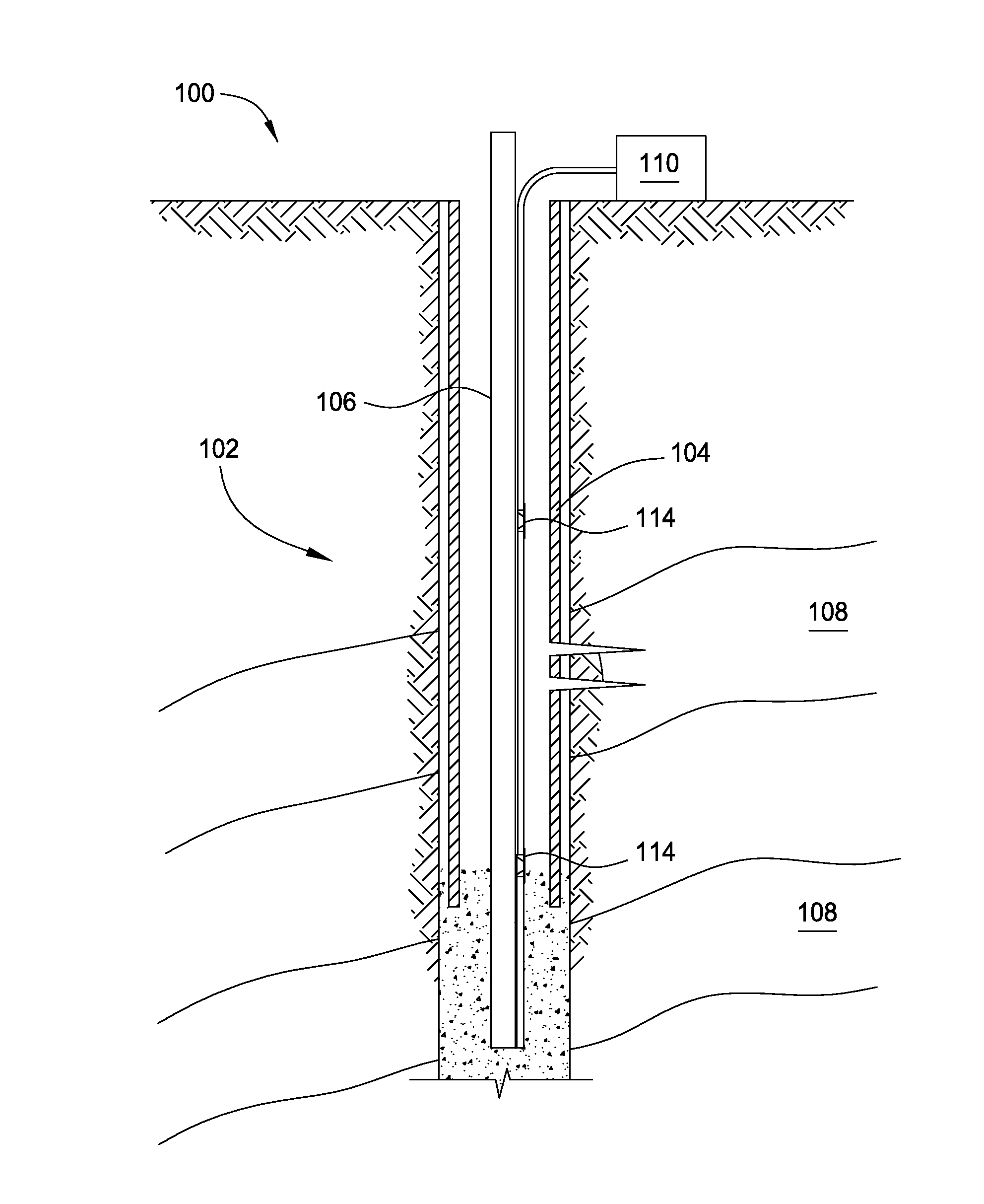
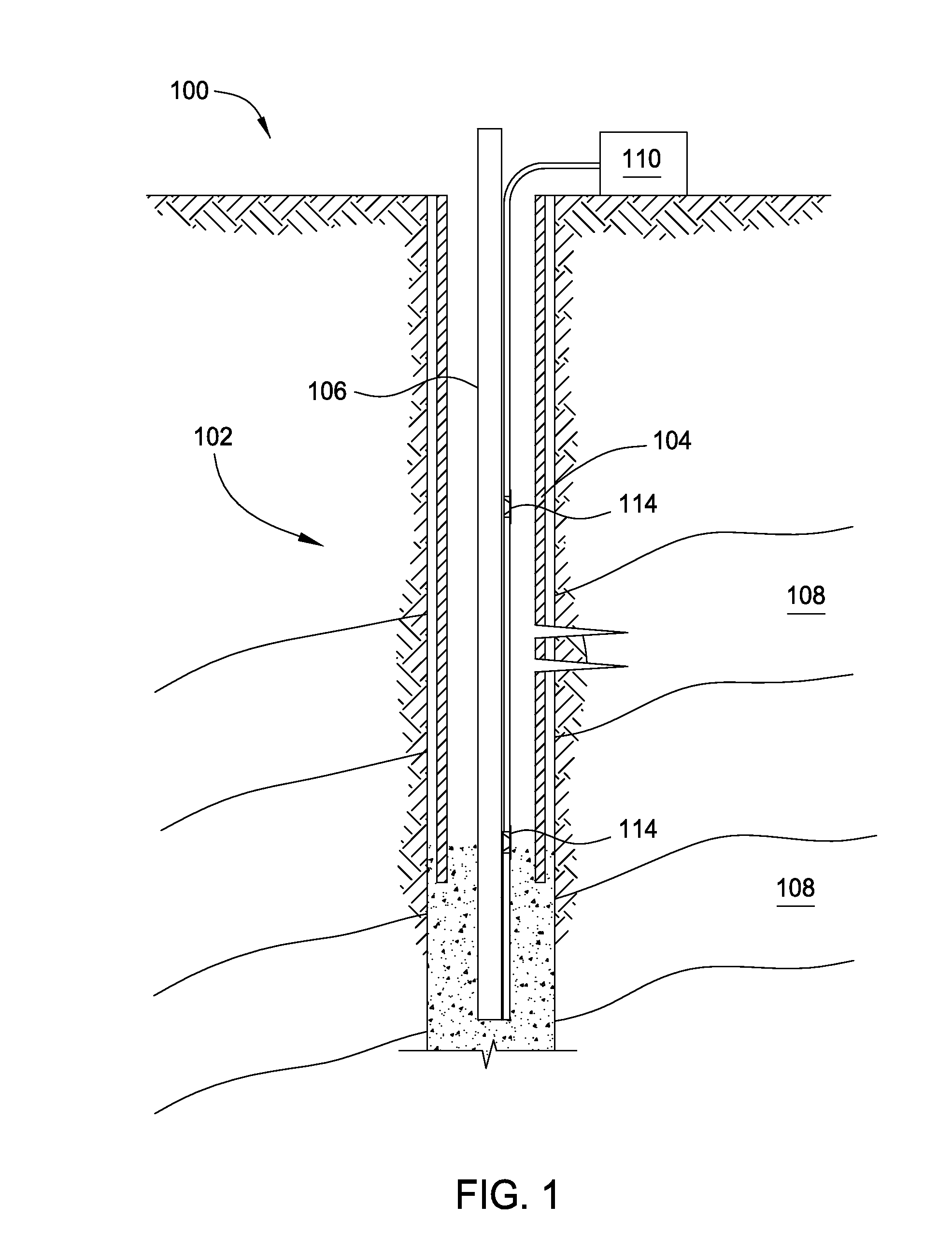
[0023]Multi-point optical sensors and distributed optical sensors have been developed and installed in wells to measure various downhole parameters. A transducer may be used to sense such downhole parameters as pressure and temperature (e.g., P / T gauge). Conventionally, multiple optical single-ended transducers (OSETs) cannot be measured using a single optical fiber deployed down a well. Instead, optical pass-through transducers are used such that light entering one end of a particular transducer is available at the other end of this transducer for the next transducer coupled thereto. In this manner, multiple optical pass-through transducers can be measured using a single optical fiber reaching the surface. However, if one of the optical pass-through transducers is damaged such that light will no longer travel through, then light will not reach transducers located further downhole, limiting the sensing information available.

[0024]Accordingly, what is needed are techniques and appara...


PUM


Abstract

Techniques and apparatus are provided for downhole sensing using optical couplers in a downhole splitter assembly to split interrogating light signals into multiple optical sensing branches. Each optical branch may then be coupled to an optical sensor (e.g., a pass-through or an optical single-ended transducer (OSET)) or to another optical coupler for additional branching. The sensors may be pressure/temperature (P/T) type transducers. Some systems may exclusively use OSETs as the optical sensors. In this manner, if one of the OSETs is damaged, it does not affect light traveling to any of the other sensors, and sensing information from remaining sensors is still returned.

Description

CROSS-REFERENCE TO RELATED APPLICATIONS[0001]This application claims benefit of U.S. Provisional Patent Application Ser. No. 61 / 824,541, filed May 17, 2013 and entitled “OPTICAL COUPLERS USED IN A DOWNHOLE SPLITTER ASSEMBLY,” which is herein incorporated by reference.BACKGROUND OF THE INVENTION[0002]1. Field of the Invention[0003]Embodiments of the present invention generally relate to downhole sensing and, more particularly, to optical couplers used in a downhole splitter assembly.[0004]2. Description of the Related Art[0005]The world's reservoirs are aging. This translates to increased water production and gas coning, increased lifting costs, expensive treatment of produced water, and high cost of deferred or lost hydrocarbon production. Hence, it is becoming increasingly important to accurately measure and understand conditions inside a well, reservoir, or field. Downhole sensing offers measurement near the areas of interest—e.g., near the wellbore or reservoir—and thus offers po...

Claims


Application Information

Patent Timeline
Patent Type & Authority Applications(United States)
IPC IPC(8): G01V8/00
CPCG01V8/00G02B6/36G01L9/0076G01L9/0077G01K11/32G01K11/3206G01D5/35316G01D5/35387G01D5/35354E21B47/113E21B47/135G02B6/28G02B6/44E21B47/114
Inventor LAGACE, MICHAELLABELLA, DAVIDTAVERNER, DOMINO
Owner WEATHERFORD TECH HLDG LLC
Why Eureka
Try Eureka