Vehicle wheel

a technology of vehicle wheels and airflow guides, which is applied in the direction of disc wheels, wheel protection, vehicle components, etc., can solve the problems of minor poor effect of reducing wind resistance by using airflow guide holes or air passages to guide airflow, and noise inside and outside the wheel, so as to reduce driving noise, increase airflow, and reduce fuel consumption.

Active Publication Date: 2014-11-20
CHEN KUAN TING
View PDF3 Cites 8 Cited by
  • Summary
  • Abstract
  • Description
  • Claims
  • Application Information

AI Technical Summary

Benefits of technology

[0005]The primary object of the present invention is to provide a structure of vehicle wheel, which improves the conventional wheels in respect of wind resistance and push-assisting force in the forward rotation direction of the wheel in order to achieve the purposes of reducing driving noise, assisting forward movement of vehicle, and reducing fuel consumption.
[0006]To achieve the above object, the present invention provides a vehicle wheel, which comprises a wheel body and a plurality of rim blades, wherein the plurality of rim blades are coupled to at least one side surface of the wheel body and each of the rim blades comprises at least one airflow guide section and at least one airflow-assisting section. The airflow guide section and the airflow-assisting section are arranged in the form of front and rear series formed on the rim blade. When the vehicle wheel is coupled with a tire, the airflow guide section is located at the side of the rim blade facing the forwarding direction of the rotation of the tire and the airflow-assisting section is located at the side of the rim blade that is opposite to the forwarding direction of the rotation of the tire so as to increase airflow, reduce wind resistance, and reduce noise and also to induce compliant airflow guidance and push-assisting forces to achieve the purpose of reducing fuel consumption of the operation of the vehicle and to ensure stability of operation of the vehicle.
[0007]The efficacy of the vehicle wheel of the present invention is that each of the rim blades is provided with a structure comprising an airflow guide section and an airflow-assisting section where the airflow guide section is located at the side of the rim blade that faces a forwarding direction of the rotation of the wheel and the airflow-assisting section is located at the side of the rim blade that is opposite to the forwarding direction of rotation of the wheel so as to increase airflow and reduce wind resistance and also generate a push-assisting force for compliantly guiding the rotation of the vehicle to assist the movement of the vehicle, reduce the fuel consumption, and stabilize the movement of the vehicle thereby improving the problem of the conventional vehicle wheel in respect of wind resistance of the wheel, reducing the noise generated by wheel during movement, reducing fuel consumption of the vehicle. Further, the vehicle wheel of the present invention is attachable to a wheel and is not constrained to specific model, brand, or brake system of the vehicle so as to further improve the economic value thereof for use in industry.

Problems solved by technology

However, the effectiveness of reduction of wind resistance by using airflow guide holes or air passage to guide airflows is actually poor and may induce turbulences inside and outside the wheel and noises.
They only provide a minor effect of reducing wind resistance and actually have no way to substantially reduce wind resistance and to take advantage of air guidance to make the wheel assisting the vehicle to move better.
Further, these known designs provide no individual airflow guide structures for left-side and right-side wheels, so that although the wheel on one side of the vehicle may have an effect of reducing wind resistance, yet the wheel on the opposite side may have an adverse effect of increasing wind resistance, whereby the effects of reducing and increasing wind resistance offset each other, giving no net reduction of wind resistance.
Further, these known wheels or wheel structures are provided for passively reducing wind resistance against the wheel and they do not intend to make the vehicle wheels to generate an assisting force when the vehicle is being driven.
Thus, they do not have an effect of providing a push assisting force to achieve reduction of fuel consumption.
A vehicle equipped with such wheels consumes the same amount of fuel and energy in driving as any existing vehicles.

Method used


Image

  • Vehicle wheel
  • Vehicle wheel
  • Vehicle wheel

Examples


first embodiment

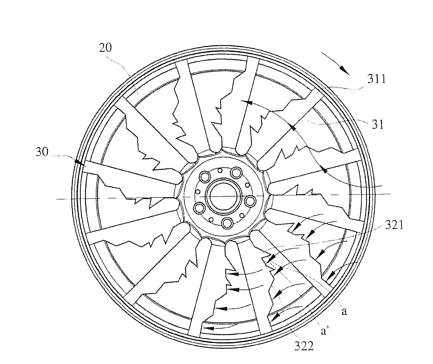
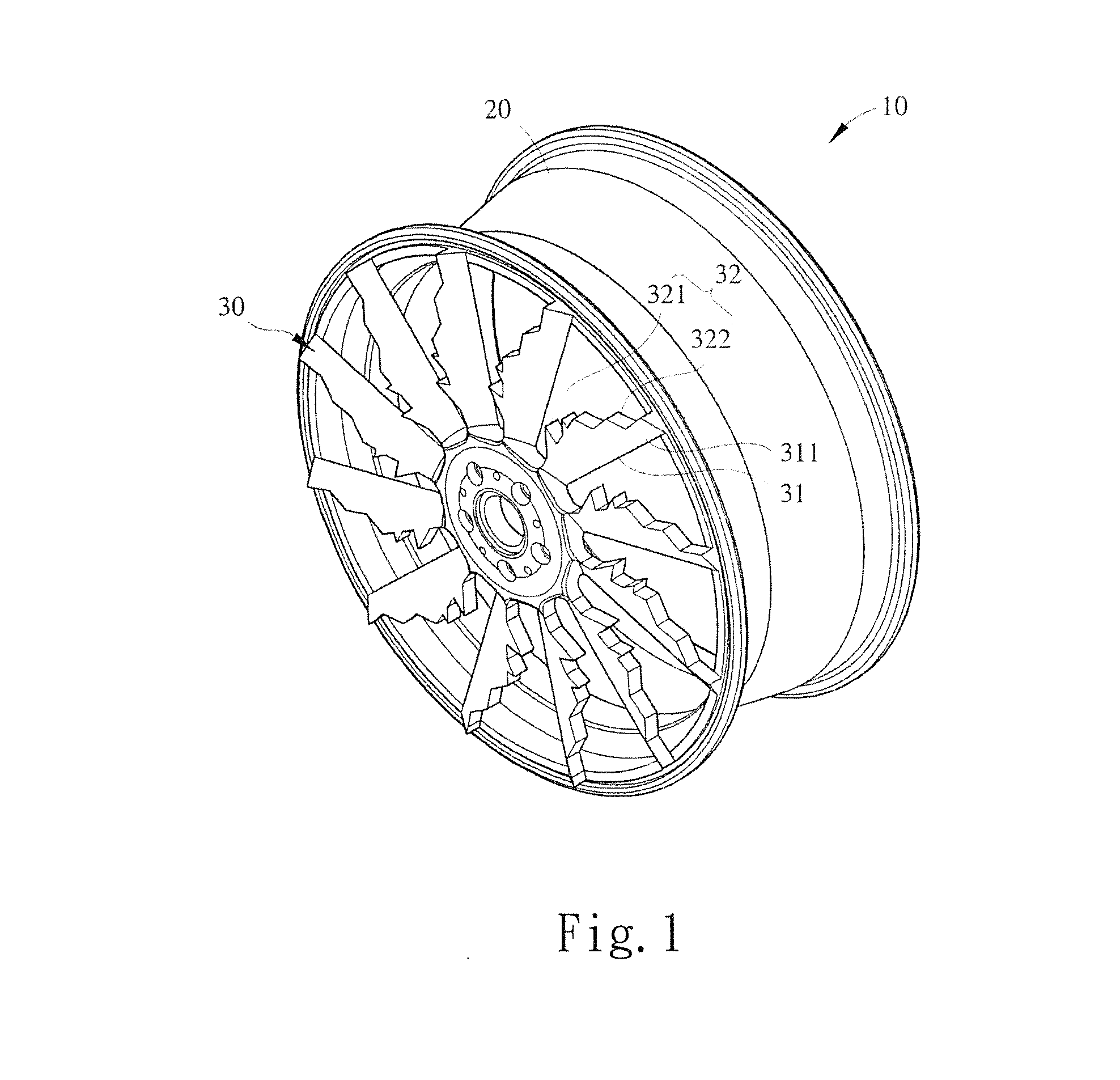
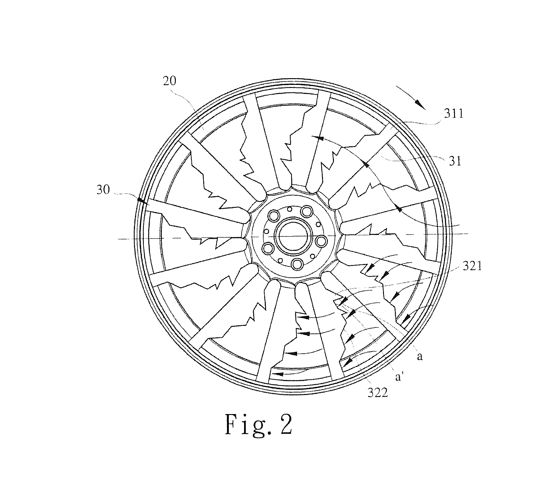
[0033]With reference to the drawings and in particular to FIGS. 1, 2, 3, 4, 5, and 6A-6D, which show a vehicle wheel 10 constructed in accordance with the present invention, the vehicle wheel 10 comprises a wheel body 20 and a plurality of rim blades 30 integrally formed with and mounted to an outside surface of the wheel body 20. The rim blades 30 are formed to integrally couple with at least one side surface of the wheel body 20 and in the present invention, coupling to the outside surface of the wheel body 20 is given as an example for explanation. Each of the rim blades 30 comprises at least one airflow guide section 31 and at least one airflow-assisting section 32, wherein the airflow guide section 31 and the airflow-assisting section 32 are formed on the rim blade 30 in the form of front and rear series.

[0034]The airflow guide section 31 comprises at least one slope guide surface 311 and the airflow-assisting section 32 comprises a plurality of guide blocks 321 and a plurality...

fourth embodiment

[0038]Referring to FIG. 15, which shows a vehicle wheel 10 according to the present invention, beside being integrally formed together as described above, the wheel body 20 and the plurality of rim blades 30 of the vehicle wheel 10 according to the present invention can be made such that the plurality of rim blades 30 is integrally formed with a rim module 102. The rim module 102 has a circumference and a plurality of snap-fitting elements 103. The snap-fitting elements 103 can be snap-fit to a recess of an inner rim of an outside surface of the wheel body 20 to have the rim module 102 coupled to the outside surface of the wheel body 20 so that the plurality of rim blades 30 and the wheel body 20 are coupled in a two-piece removable fitting arrangement and two sides of the wheel body 20 can each receive a rim module 102 having a plurality of rim blades 30 to removably snap-fit thereto. Thus, according to different mode, brands, driving conditions, or mounting to left or right wheels...

fifth embodiment

[0040]Referring to FIG. 16, which shows a vehicle wheel 10 according to the present invention, the rim module 102 having a plurality of rim blades 30 integrally formed therewith shown in FIG. 15 comprises a threaded hole 104 formed in a surface of at least one of the rim blades 30. The wheel body 20 has an outside surface in which at least one locking hole 105 is formed. The threaded hole 104 and the locking hole 105 are set in alignment with each other and a fastener, such as bolt or a screw (not shown), is used to fasten them together so as to secure the rim module 102 to the outside surface of the wheel body 20. A similar arrangement of two-piece removably assembled or disassembled structure of the rim module 102 and the wheel body 20 shown in FIG. 15 can be achieved for the rim blades 30. In other words, according to different mode, brands, driving conditions, or mounting to left or right wheels of vehicle, different rim modules 102 having different arrangements of rim blades 30...


PUM


Abstract

A vehicle wheel includes a wheel body and a plurality of rim blades. The plurality of rim blades is coupled to at least one side surface of the wheel body. Each of the rim blades is provided with at least one airflow guide section and at least one airflow-assisting section. The airflow guide section and the airflow-assisting section are arranged in the form of front and rear series on the rim blade. When the vehicle wheel is coupled with a tire, the airflow guide section is located at the side of the rim blade facing a forwarding direction of rotation of the wheel and the airflow-assisting section is located at the side of the rim blade opposite to the forwarding rotation of the wheels. As such, airflow is increased, wind resistance is reduced, and noise is reduced.

Description

BACKGROUND OF THE INVENTION[0001]1. Field of the Invention[0002]The present invention relates to a vehicle wheel, and in particular to a structure of vehicle wheel that comprises a wheel body of which a side comprises a plurality of rim blades attached thereto in such a way that the rim blades help guide airflows to reduce wind resistance and noise and also to provide an assisting force for forward movement.[0003]2. The Related Arts[0004]There are a great number of modes and types of automobile wheels, but most of them put emphasis on the outside appearance or the shape thereof. Although some vehicle wheels are designed and claimed to provide an effect of reducing wind resistance, most of them are better in decoration than actually reducing wind resistance. For example, Taiwan Utility Model M362122, which discloses a carbon fiber wheel that reduces side wind resistance, and Taiwan Utility Model 254216, which discloses a novel wheel, both uses airflow guide holes or air passage struc...

Claims


Application Information

Patent Timeline
Patent Type & Authority Applications(United States)
IPC IPC(8): B60B7/00B60B7/06
CPCB60B7/063B60B7/0066B60B19/10B60B3/10B60B7/0086B60B7/065B60B7/08B60B2900/1216Y02T10/88B60B3/00B60B7/00B60B7/002B60B19/00
Inventor CHEN, KUAN-TING
Owner CHEN KUAN TING
Why Eureka
Try Eureka