Digital phase-locked loop device with automatic frequency range selection

a phase-locked loop and automatic technology, applied in the direction of electrical equipment, pulse automatic control, etc., can solve the problems of lock time, phase stability, width of the frequency range of outputted signals, etc., and achieve the effect of faster convergence and faster convergence of frequency range selection

Active Publication Date: 2014-11-20
ASAHI KASEI ELECTRONICS CO LTD
View PDF0 Cites 11 Cited by
  • Summary
  • Abstract
  • Description
  • Claims
  • Application Information

AI Technical Summary

Benefits of technology

[0029]In some embodiments, the DCO controller may be further adapted for disabling a low-pass filter function of the digital loop filter during the frequency range selection operation which relates to the coarsest one of the capacitor sub-ranks. Accordingly, in some embodiments, faster convergence of the frequency range selection may be obtained.
[0030]In some embodiments, the DCO controller may be further adapted for handling additional capacitance maximum and minimum values for each capacitor sub-rank other than the finest sub-rank. The additional capacitance maximum (resp. minimum) value thus implemented corresponds to a combination of the respective maximum (resp. minimum) capacitance values which are available for the capacitor sub-rank currently under frequency range selection and for each capacitor sub-rank finer than this latter. Then, these additional capacitance maximum and minimum values are available for being selected by the DCO controller during the frequency range selection operation currently executed. Accordingly, in some embodiments, faster convergence for the frequency range selection can thus be obtained for frequency values which are close to the limits of the total frequency range available.

Problems solved by technology

General issues for PLLs include the width of the frequency range of the outputted signal, the lock time and the phase stability.
This extra-circuit increases the overall device complexity and cost.
The switching between both operations then generates a phase jump which may cause nuisances to the PLL application.

Method used


Image

  • Digital phase-locked loop device with automatic frequency range selection
  • Digital phase-locked loop device with automatic frequency range selection
  • Digital phase-locked loop device with automatic frequency range selection

Examples


Embodiment Construction

[0043]Reference will now be made in detail to embodiments, examples of which are illustrated in the accompanying drawings. In the following detailed description, numerous non-limiting specific details are set forth in order to assist in understanding the subject matter presented herein. It will be apparent, however, to one of ordinary skill in the art that various alternatives may be used without departing from the scope of the present invention and the subject matter may be practiced without these specific details.

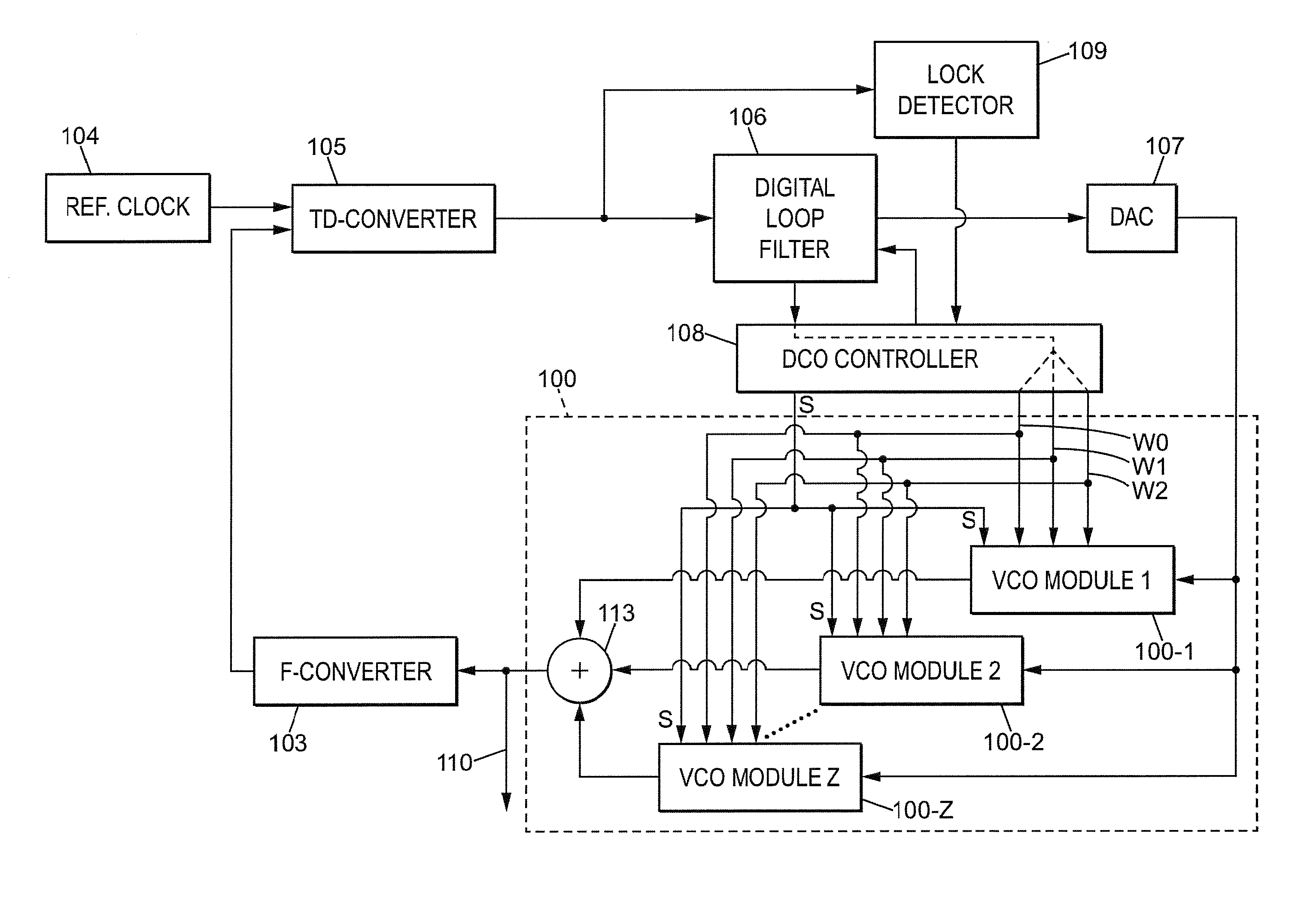
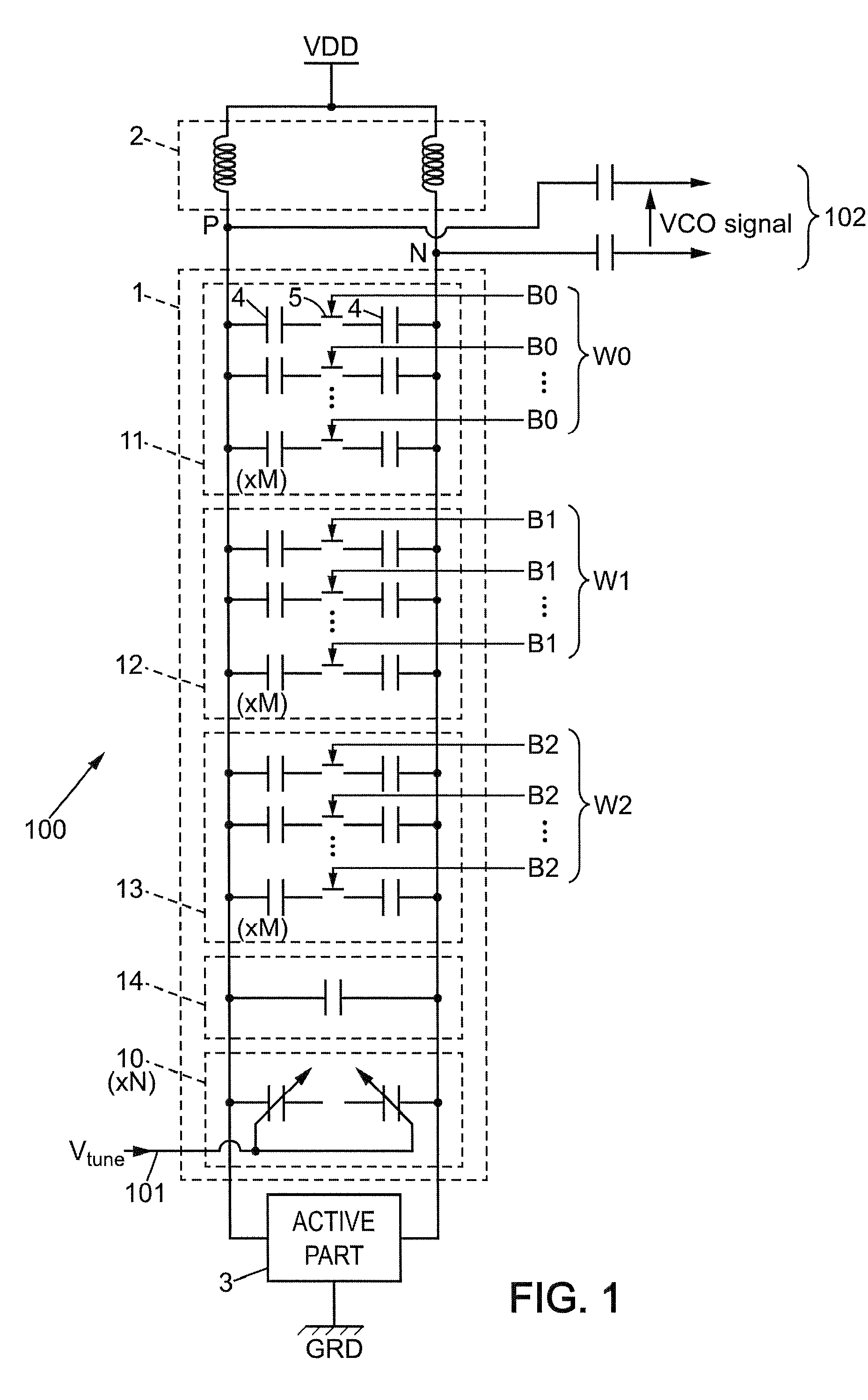
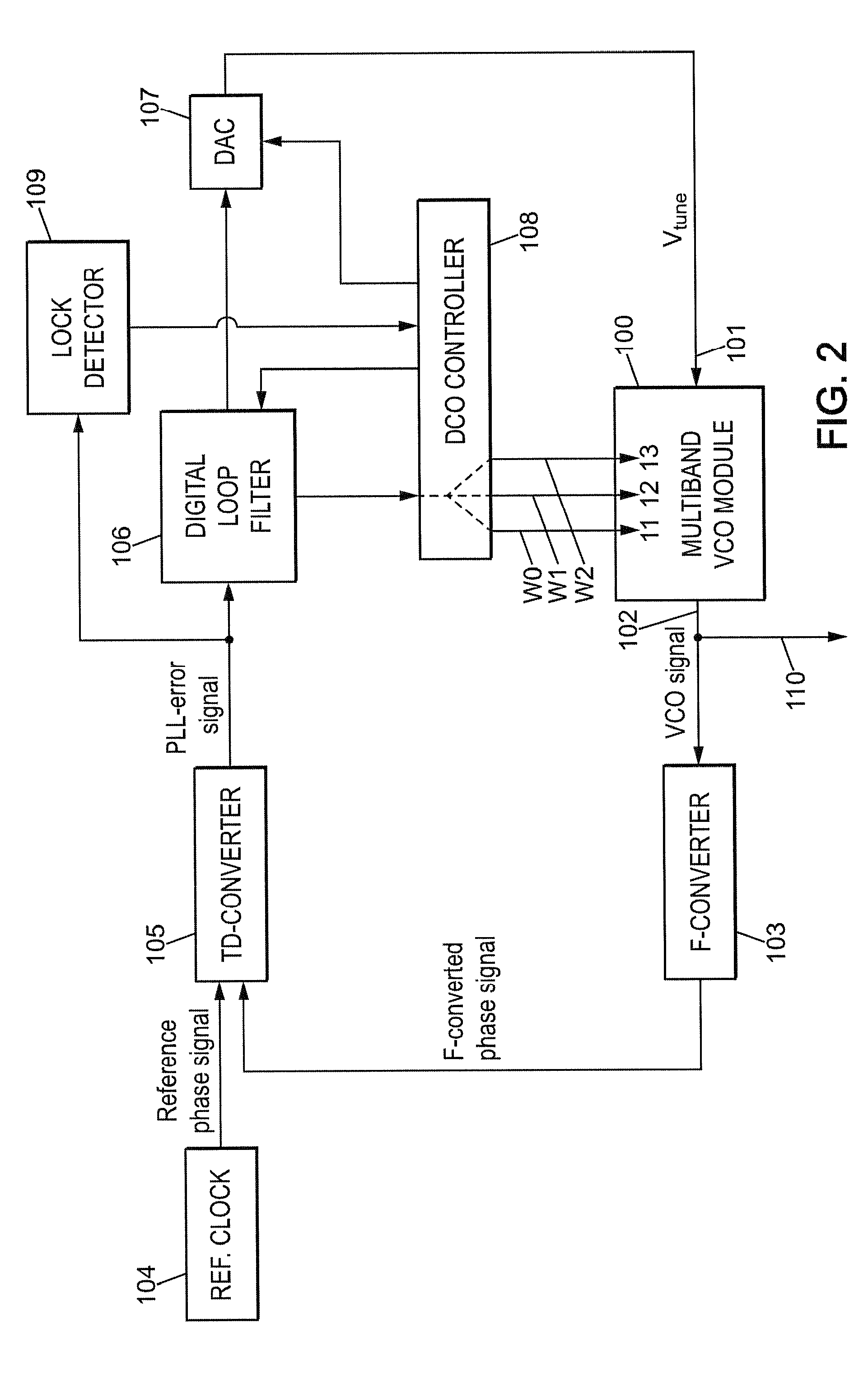
[0044]In some embodiments, the multiband feature of the DPLL device results from using one multiband VCO module which is provided with digitally-controlled capacitor tank. FIG. 1 illustrates an exemplary general structure of such multiband VCO module, denoted 100 as a whole, and which may be of differential type for improved noise reduction. The VCO module 100 is comprised of a capacitor module 1, an inductor module 2 and an active part 3 all connected in parallel between...


PUM


Abstract

A digital phase-locked loop (PLL) device includes a digital loop filter which is provided with both a VCO-loop output and a DCO-loop output. The VCO-loop output is connected to an analog input of a multiband voltage-controlled oscillator (VCO) module for allowing usual operation of the PLL with a direct voltage acting as feedback parameter. The DCO-loop output is connected to a digital control input of the multiband VCO module for allowing automatic frequency range selection. A code value which is produced by the digital loop filter acts as feedback parameter during the frequency range selection. Rapid and precise range selection can thus be performed.

Description

[0001]This application claims the priority and benefit of EP patent application no. 13305613.5, filed on May 15, 2013, to Asahi Kasei Microdevices Corporation of Japan, entitled “Digital Phase-Locked Loop Device with Automatic Frequency Range Selection,” which is hereby incorporated by reference in its entirety.TECHNICAL FIELD[0002]The invention relates generally to a digital phase-locked loop (DPLL) device with automatic frequency range selection.BACKGROUND[0003]Phase-locked loops are master devices for providing clock circuits, and have existed in analog or digital versions for a long time. General issues for PLLs include the width of the frequency range of the outputted signal, the lock time and the phase stability.[0004]Commonly, the frequency range is set either by selecting appropriately the voltage-controlled oscillator (VCO) which is used within the PLL, or by controlling a capacitance value for a capacitor tank that is implemented within the VCO module. Implementing digital...

Claims


Application Information

Patent Timeline
Patent Type & Authority Applications(United States)
IPC IPC(8): H03L7/099
CPCH03L7/0992H03L7/093H03L7/099H03L7/103H03L7/1976H03L2207/06
Inventor CANARD, DAVIDCHARPENTIER, SEBASTIENLECUYER, MATTHIEU
Owner ASAHI KASEI ELECTRONICS CO LTD
Why Eureka
Try Eureka