Display Backlight System

a backlight system and display technology, applied in non-linear optics, lighting and heating apparatus, instruments, etc., can solve the problems of bulky display devices, affecting the efficiency and overall brightness of lighting devices, etc., and achieve the effect of improving polarization efficiency

Inactive Publication Date: 2014-11-20
KONINKLIJKE PHILIPS ELECTRONICS NV
View PDF8 Cites 31 Cited by
  • Summary
  • Abstract
  • Description
  • Claims
  • Application Information

AI Technical Summary

Benefits of technology

[0007]It is an object of the present invention to overcome this problem, and

Problems solved by technology

However, such a diffuser impairs the efficiency and the overall brig

Method used


Image

  • Display Backlight System
  • Display Backlight System
  • Display Backlight System

Examples


Embodiment Construction

[0030]As used herein, “optically anisotropic” means that the optical properties of a medium shows a dependence on the direction of propagation of light in the medium, and the state of polarization of said light within the medium can be altered. In contrast, an “optically isotropic” medium refers to a medium in which light shows no dependence on the direction of propagation, and in which the state of the polarization of light propagating within the system cannot be altered.

[0031]As used herein, “uniaxially oriented” refers to entities having axes which tend to be oriented substantially in the same direction.

[0032]As used herein, two objects being “in optical contact” means that a path of light may extend from one object to another object, optionally via another medium having refractive index similar to that of each of said objects. “Direct optical contact” is intended to mean that said path of light extends from the first object to the second object without having to pass through an ...


PUM


Abstract

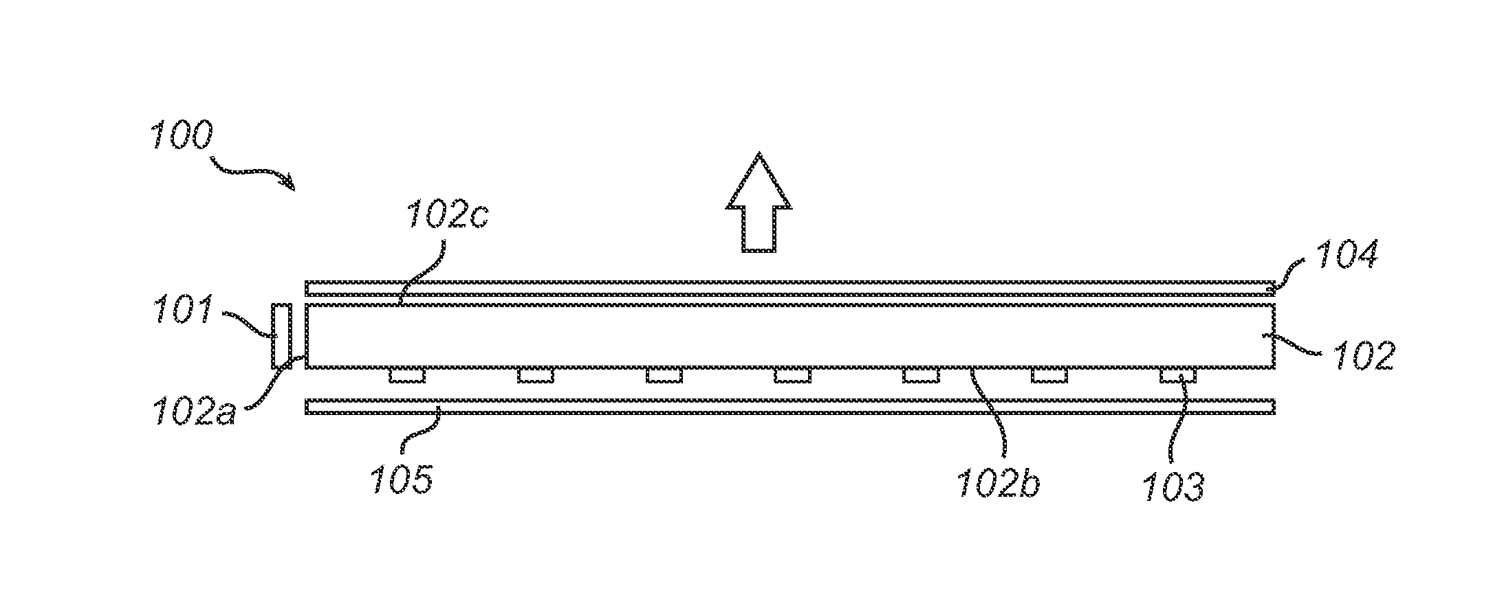
A lighting device is provided, comprising:
    • a light-emitting arrangement comprising a solid state light source capable of emitting light of a first wavelength range, and having a light outcoupling surface; and
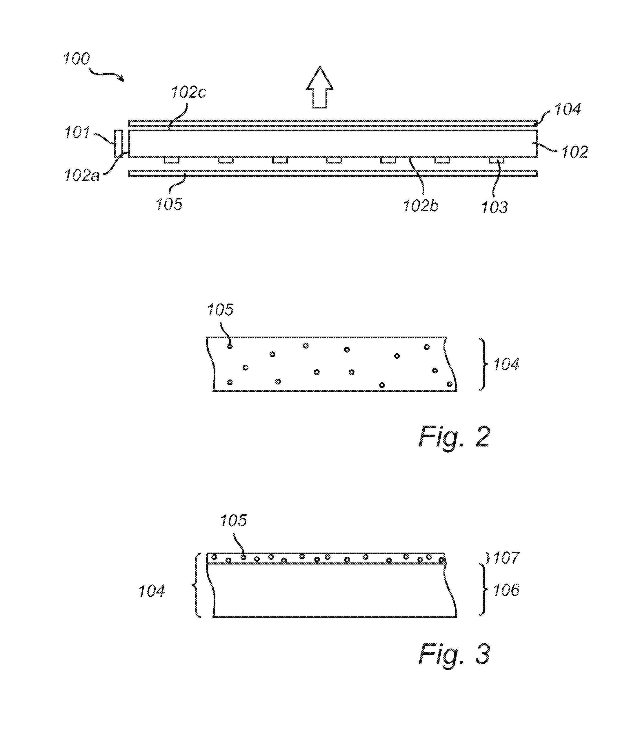
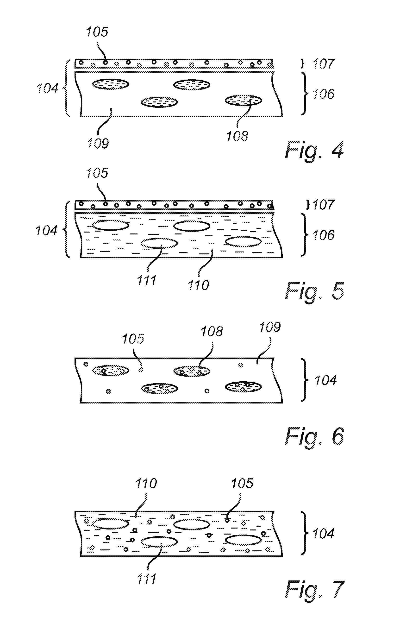
    • a polarizing color converting layer (104) arranged to receive light that is outcoupled from said light outcoupling surface, and comprising i) a color converting elements (105) capable of converting light of said first wavelength range into light of a second wavelength range, and ii) at least one region of an optically anisotropic material (108), and at least one region of an optically isotropic material (109), wherein said polarizing color converting layer is capable of preferentially scattering one linear polarization direction of light received from the light-emitting arrangement. The lighting device of the invention provides improved polarization efficiency. The lighting device may be used as a backlight in a display device, e.g. LCD device.

Description

FIELD OF THE INVENTION[0001]The present invention relates to backlights for display devices, in particular for LCD displays.BACKGROUND OF THE INVENTION[0002]Today, various types of flat-panel displays are used in a wide variety of applications, from mobile phone displays to large screen television sets. While some kinds of flat panel displays, such as so-called plasma displays, are comprised of arrays of light emitting pixels, the majority of flat-panel displays have arrays of pixels which can be switched between states but which are unable to independently emit light. Such flat-panel displays include the ubiquitously found LCD displays. In order for such flat-panel displays to be able to display an image to a user, the pixel array must be illuminated by either a so-called backlight, in the case of a transmissive-type pixel array, or, in the case of a reflective-type pixel array, by ambient light or a so-called frontlight.[0003]A conventional backlight is comprised of a planar light...

Claims


Application Information

Patent Timeline
IPC IPC(8): G02F1/1335F21V9/08F21V8/00F21V9/14
CPCG02F1/133621F21V9/14F21V9/08B82Y20/00G02F1/13362Y10S977/95G02B6/0023G02F1/133533G02B5/3008G02F1/133614
Inventor HIKMET, RIFAT ATA MUSTAFAVAN BOMMEL, TIES
Owner KONINKLIJKE PHILIPS ELECTRONICS NV
Why Eureka
Try Eureka